About halfway through the race weekend in Ohio I had noticed that the trans mainshaft had a considerable amount lateral run out. In my rush to get it together for the May deadline I did not have time for a full rebuild and was planning to do it after speed week but this forced my hand. Upon teardown the problems were apparent. Both mainshaft bearings were the original 60 year old units. These were toast, the layshaft bushings were also fairly worn with more than acceptable clearances. I had discussed with Jason the pros and cons of bushing vs needle roller bearings similar to a unit triumph over a few beers one night at his place. We did both agree that properly set up bushings are LIKLEY better than bearings, however the length of the shaft and the questionable way the 3 pieces of the transmission case mate together led me to think a concentric and repeatable bore through all pieces would be next to impossible to achieve. All tho had me calling Philadelphia Ball and Roller Bearing in the am to find some workable units, you should go there if you in the area good people. The mainshaft bearings were direct replacements and in stock on the shelf, the layshaft units were going to be ordered and some shop work was needed to use them in this box.
The drive side bearing was a direct press in just needed to add a thrust washer for the shaft the kicker side required boring the case to accept the bearing and adding a thrust washer on that side as well.
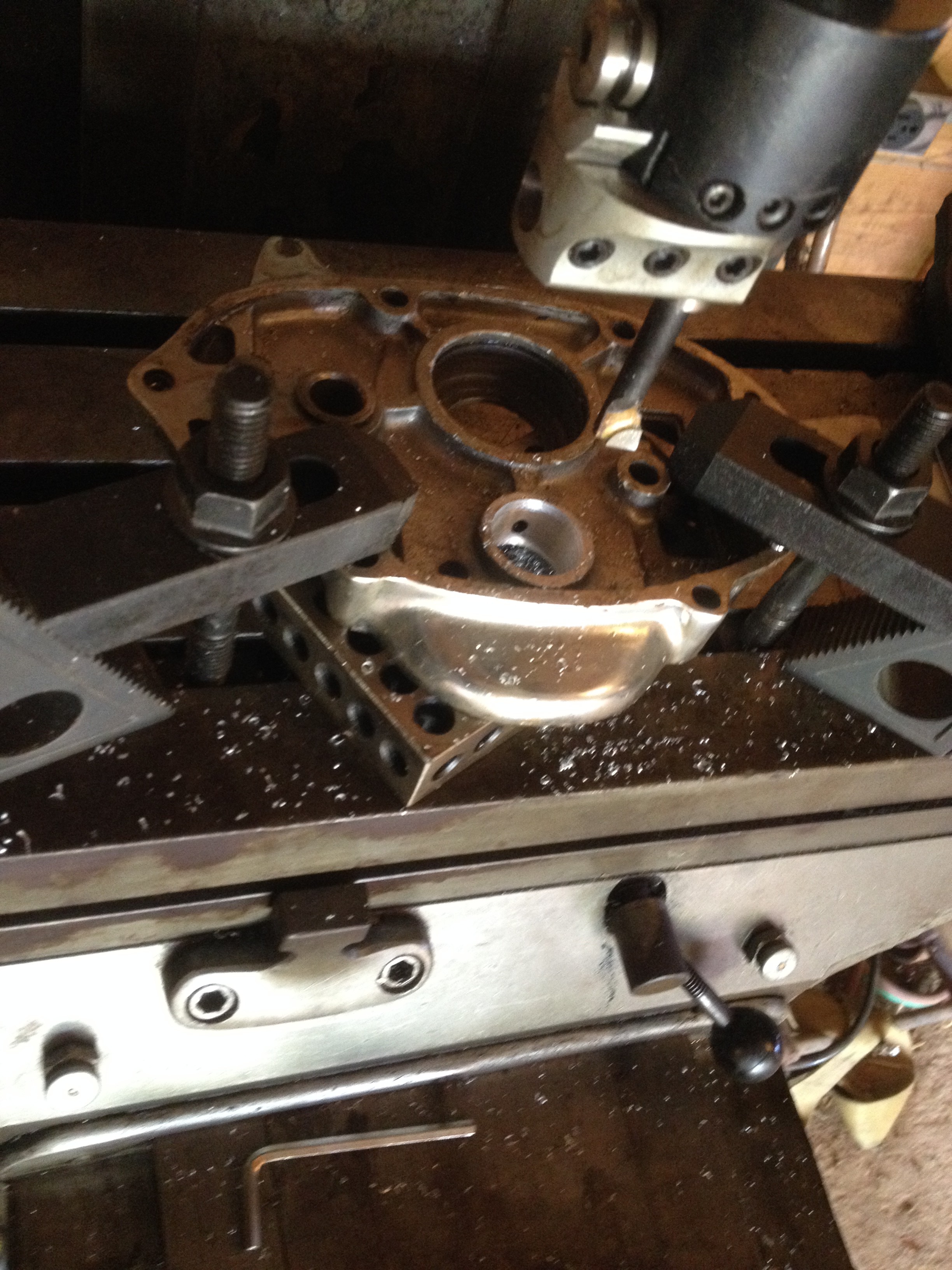
The inner cover was clamped down to the mill table, indicated true to the old bore and was opened up to allow a .002 interference fit on the new bearing
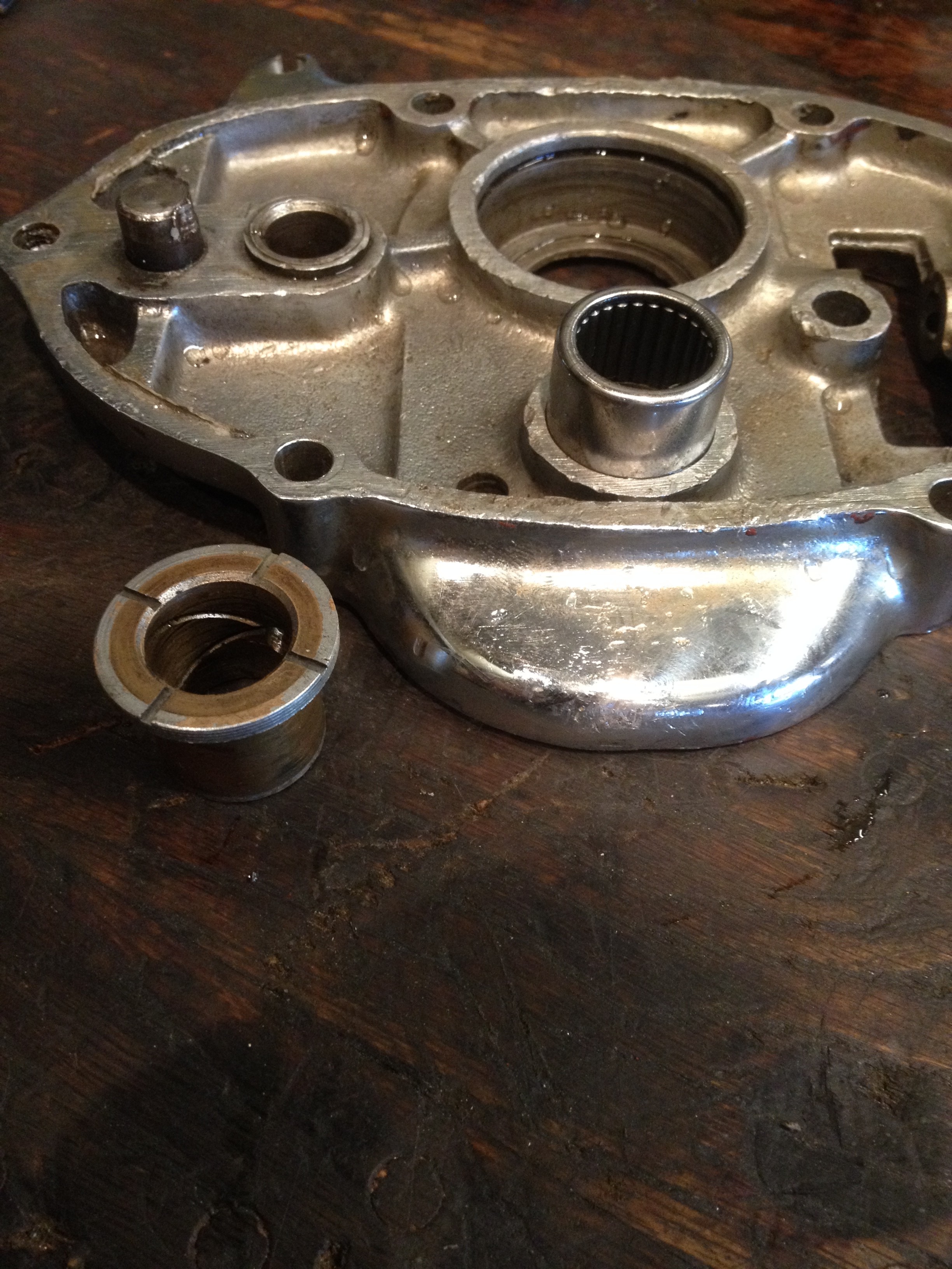
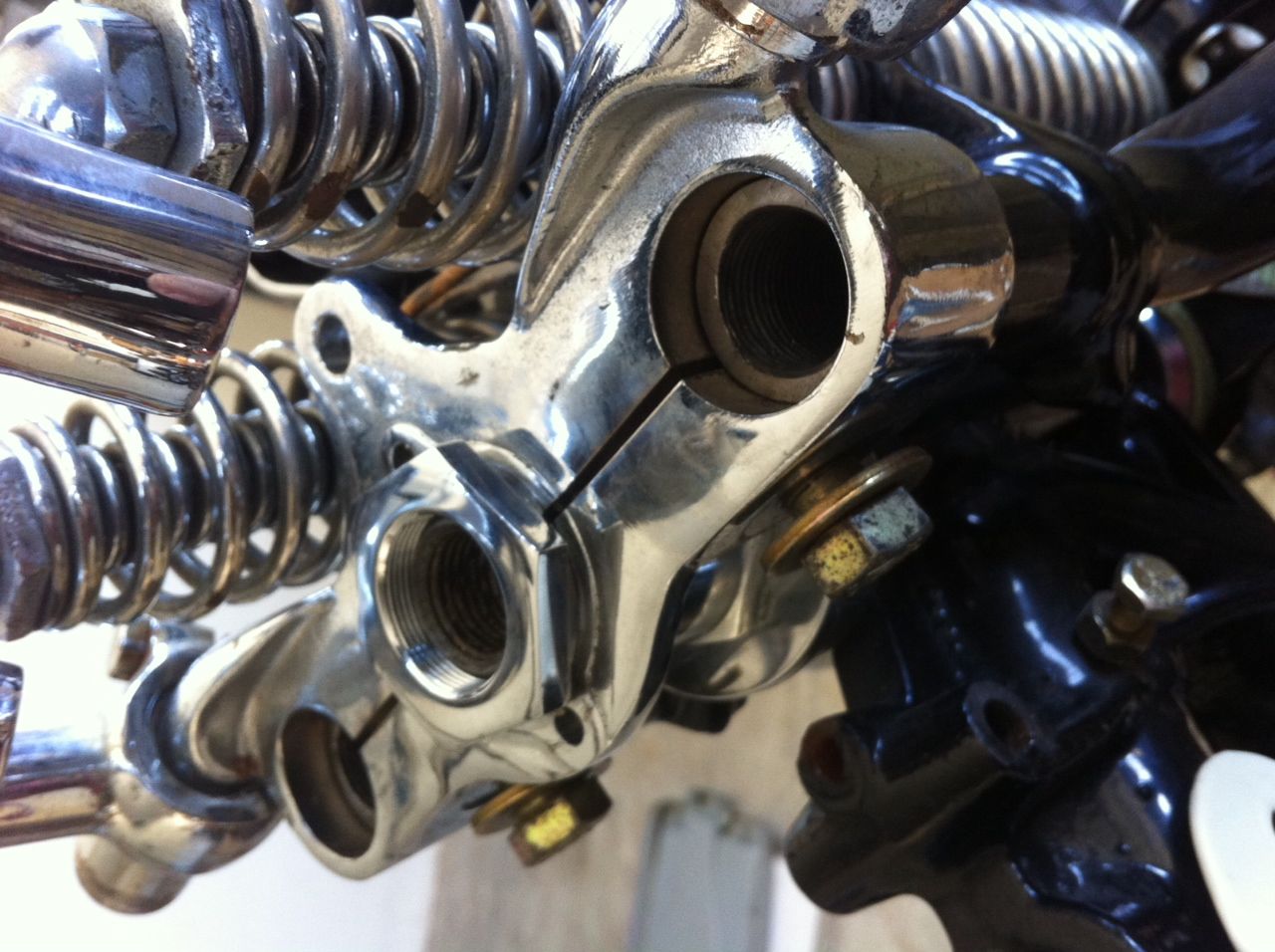
Here is the cover all bored with the bearing sitting on top and the bushing in the foreground
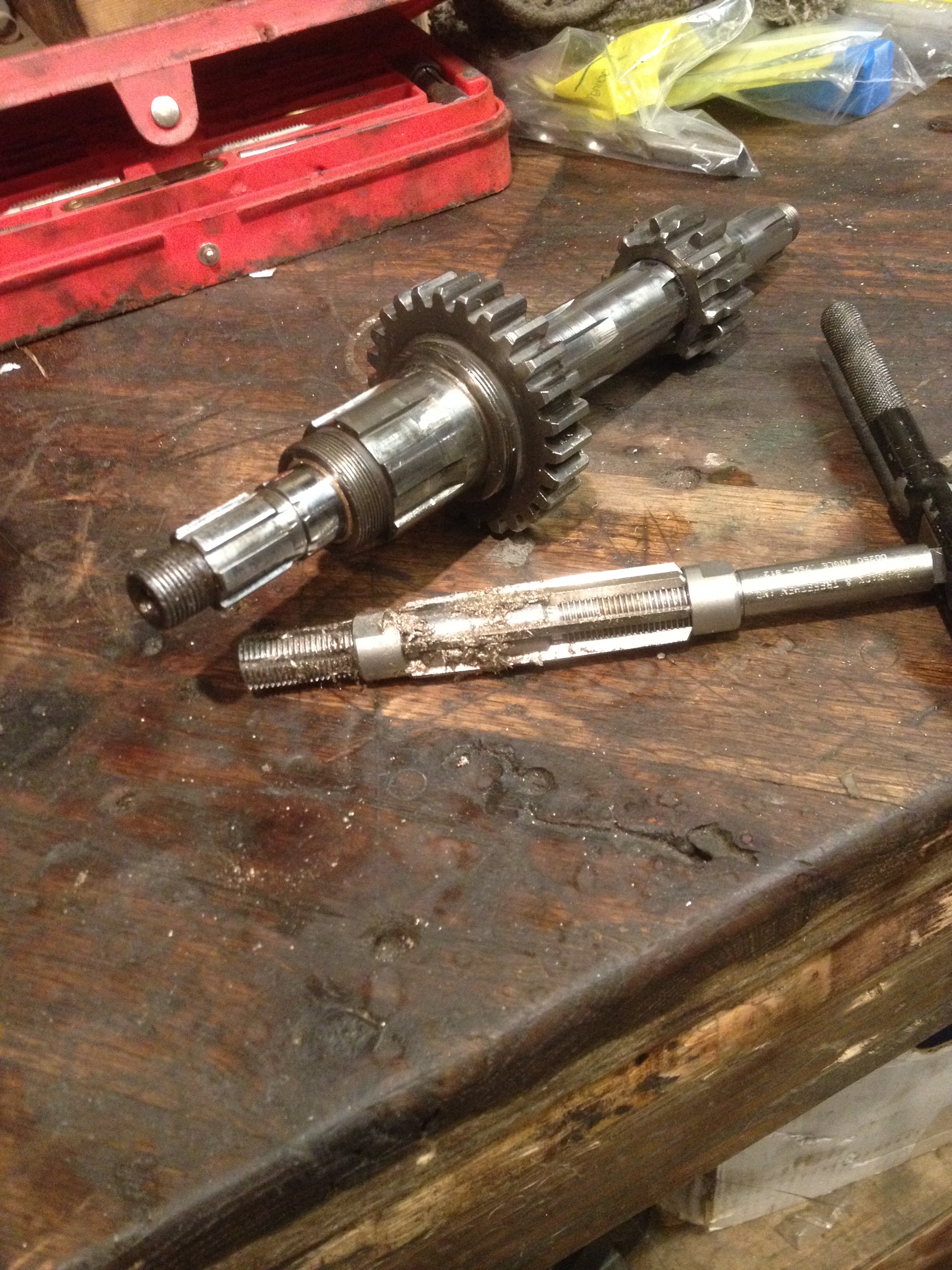
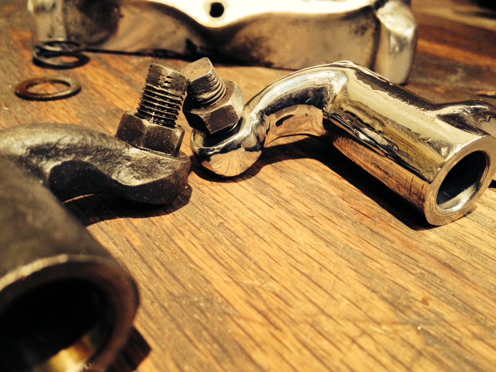
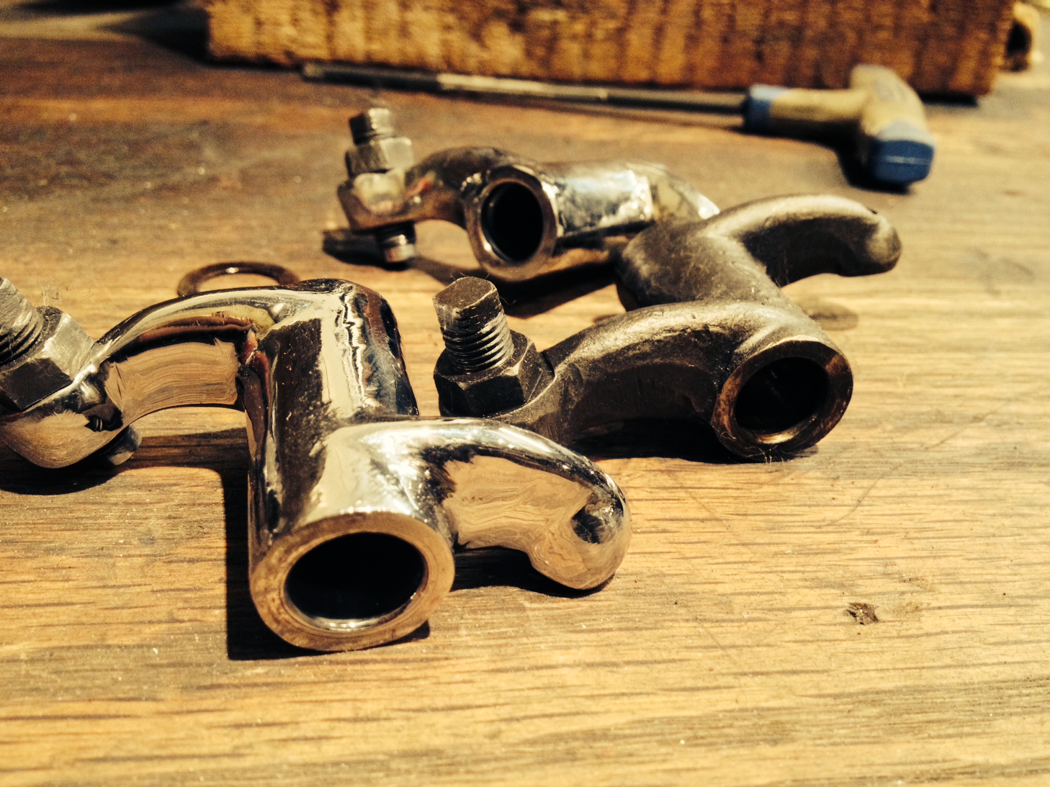
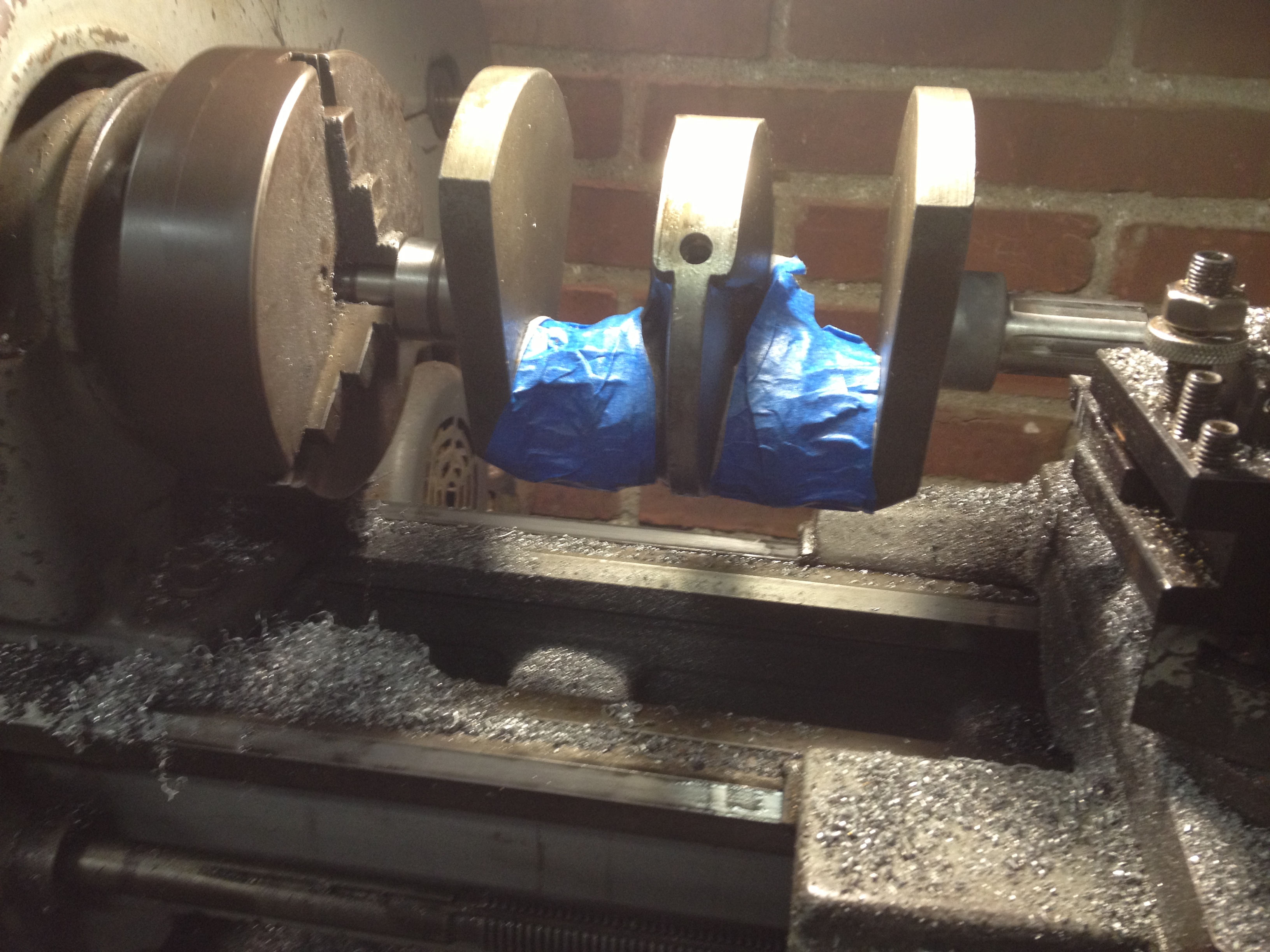
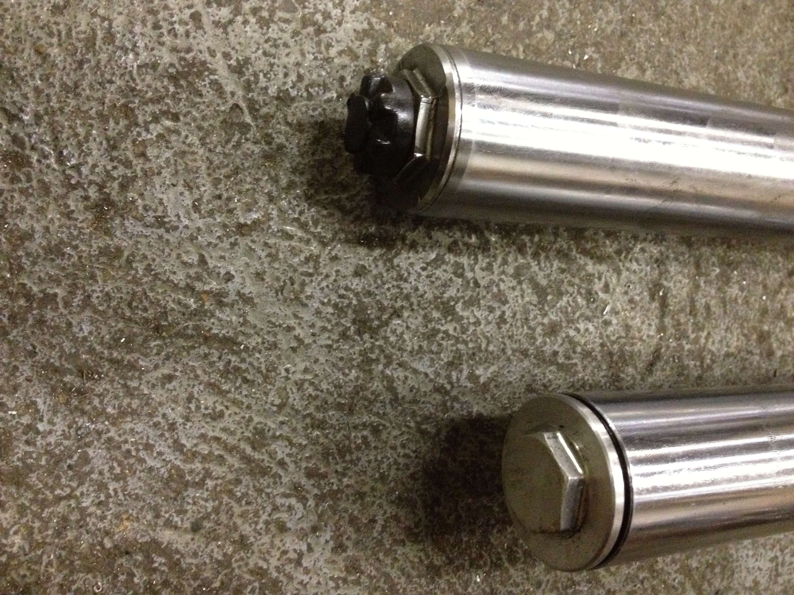
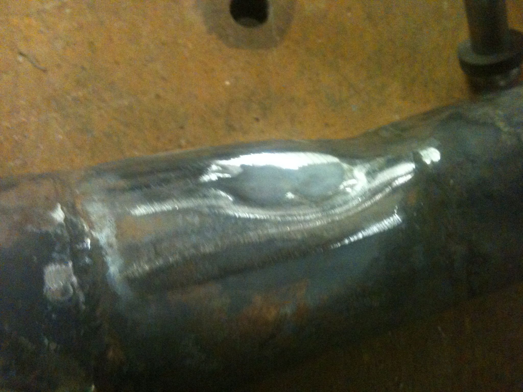
Since the trans was apart I figured I would give all the shafts and gears a polish to help reduce the drag when shifting and also so there is less windage.
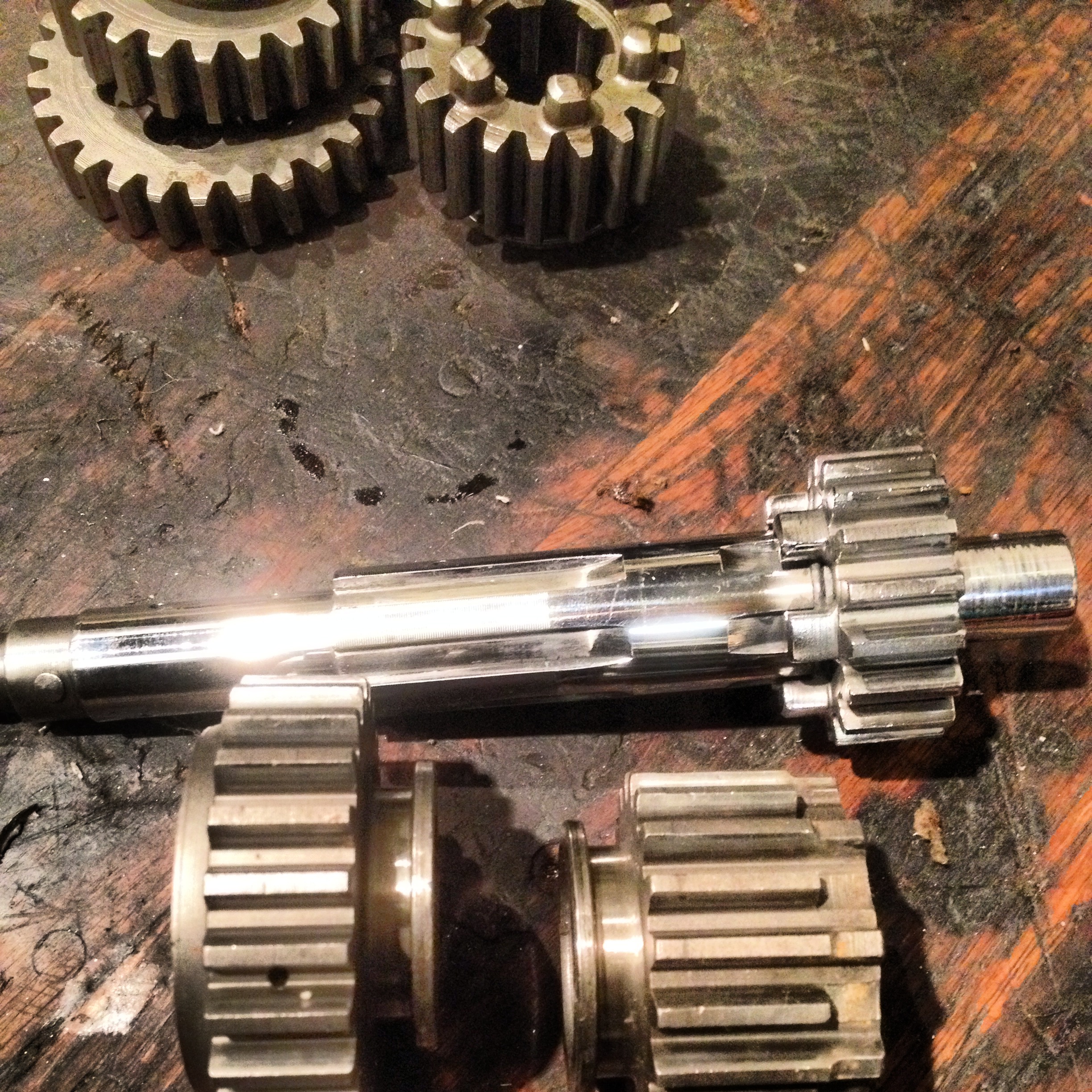
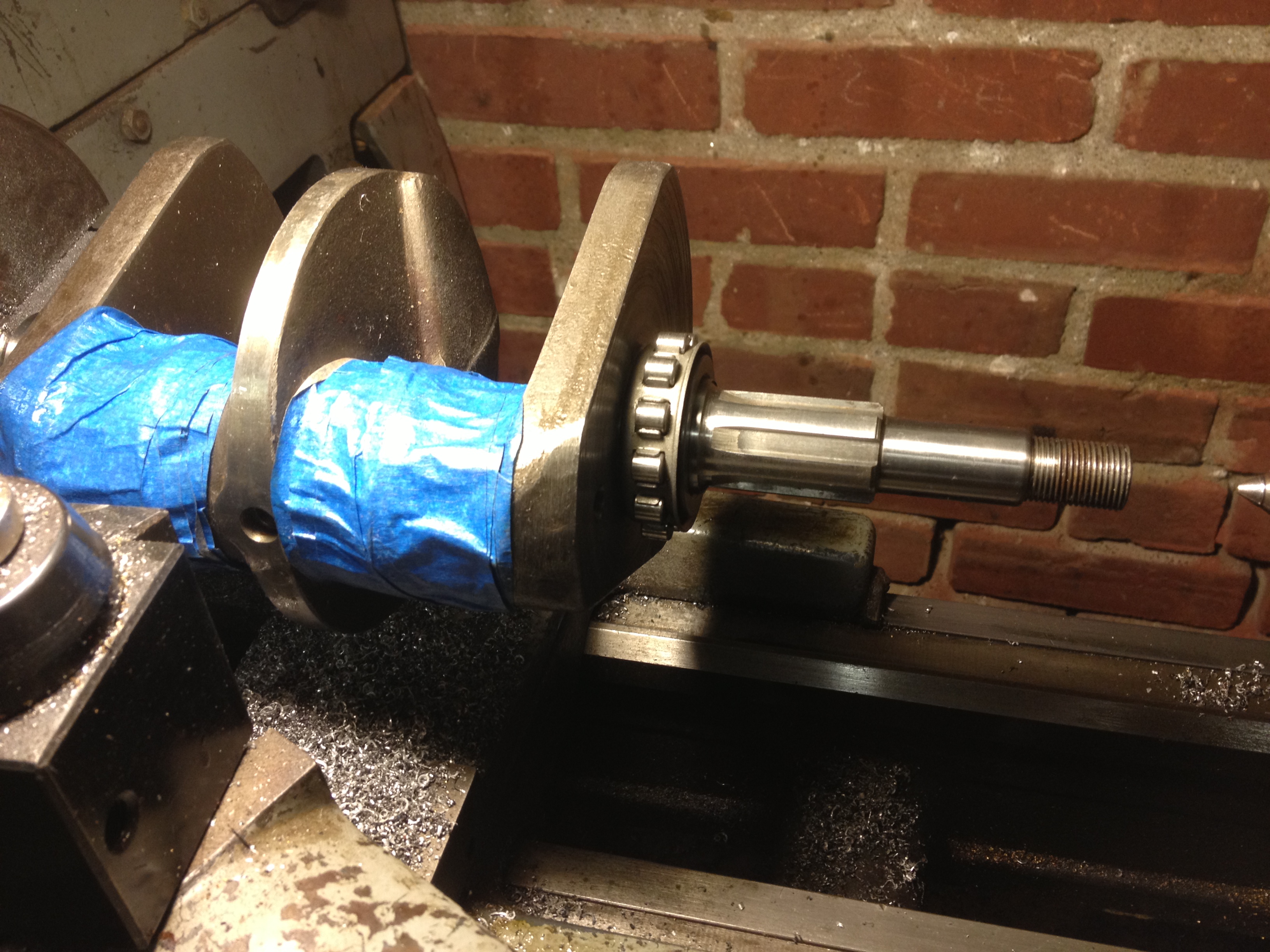
You can see the difference in the metal finish here
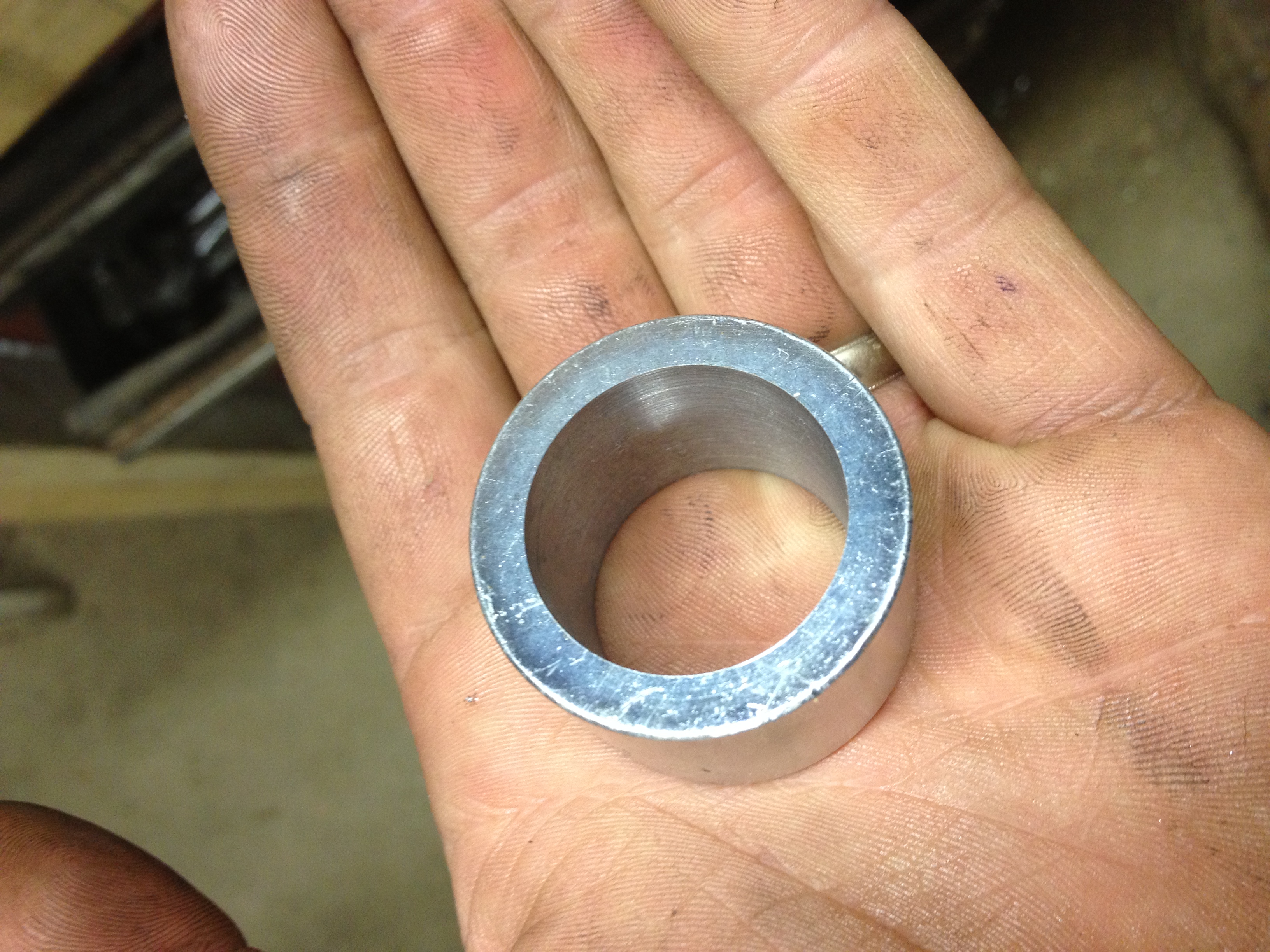
Last thing was to make up some new high gear bushes as all my sources did not stock any. This was preferable because the shaft has some wear so I could oversize the bushes to get the correct clearance.
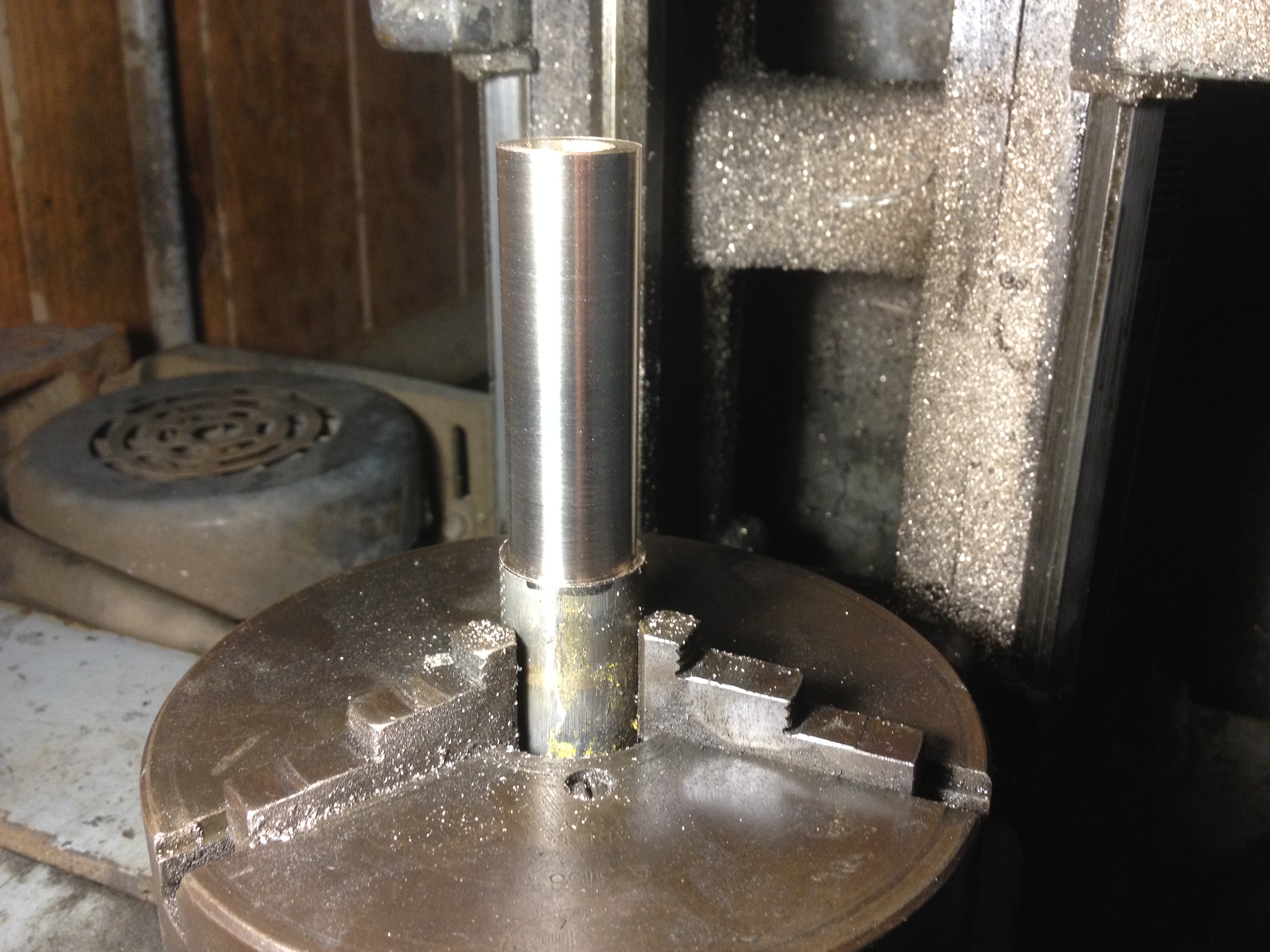
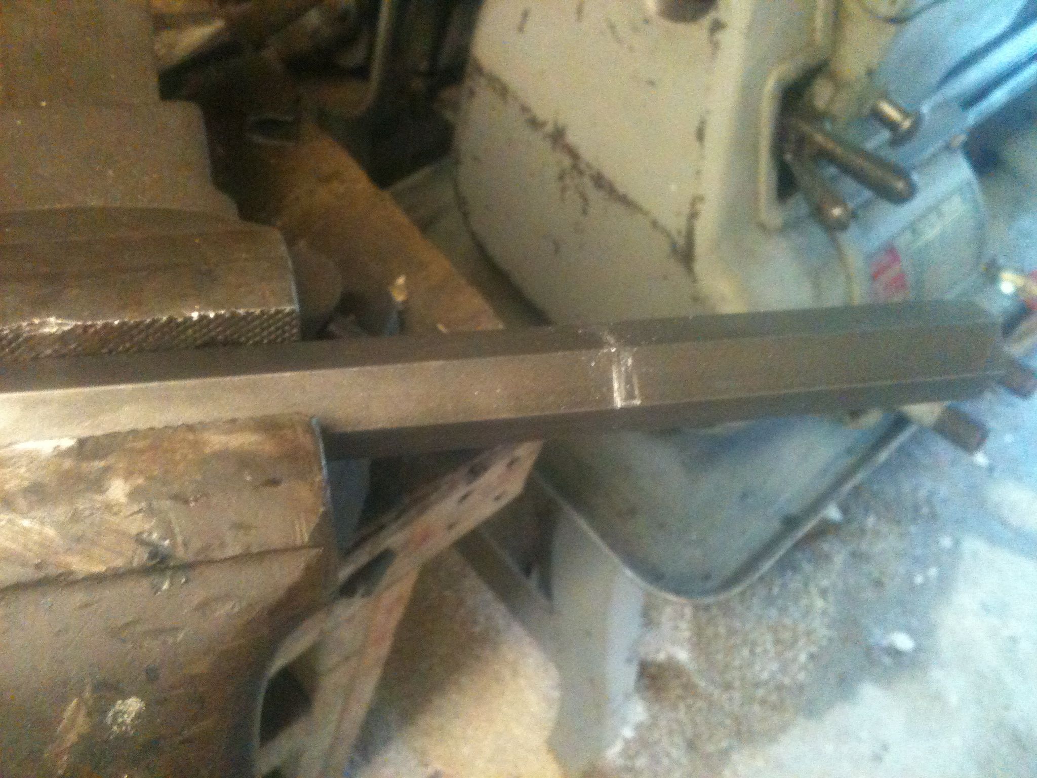
Raw 660 bronze as ordered with one cut taken to true the surface
I had thought about the best way to go about sizing the bearings. I decided the best steps would be turn outside to press fit into gear, chuck gear on ball bearing surface and bore out so both would concentric as they turn together at different speeds in use, ream to final size with .003 clearance.
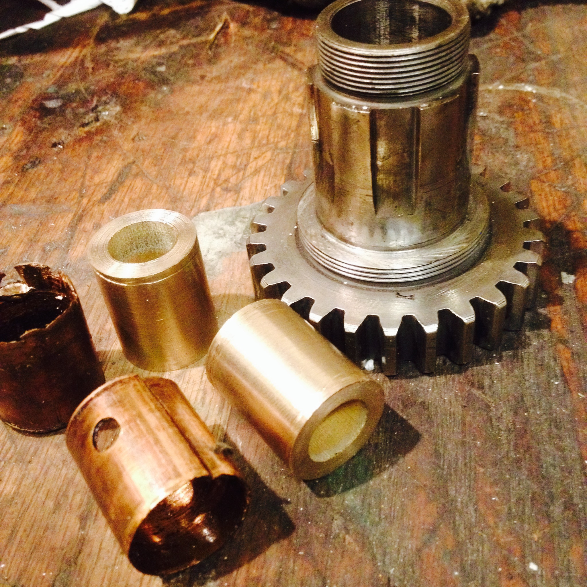
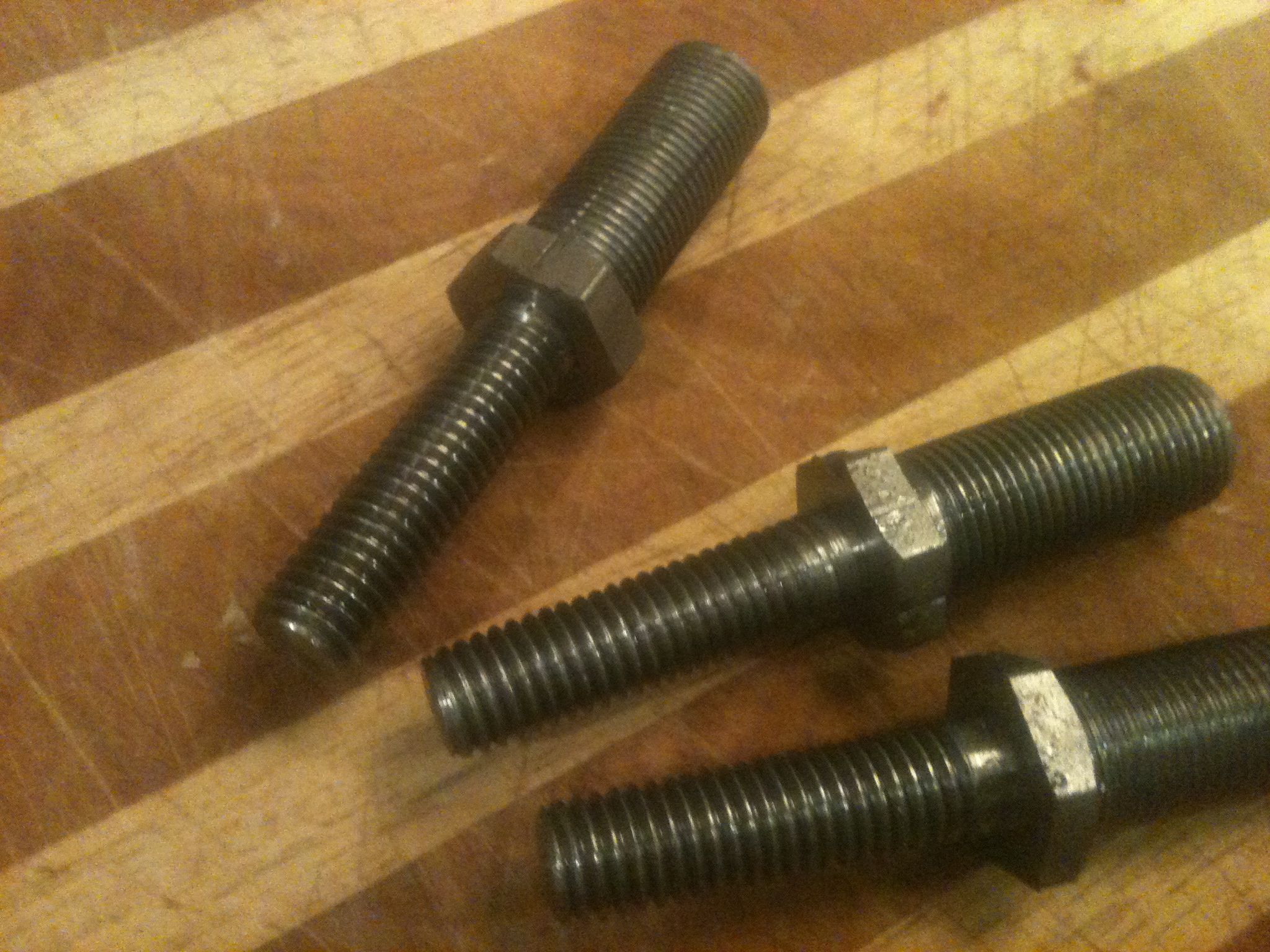
OD sized, ready to press. you can see how bad the old ones were
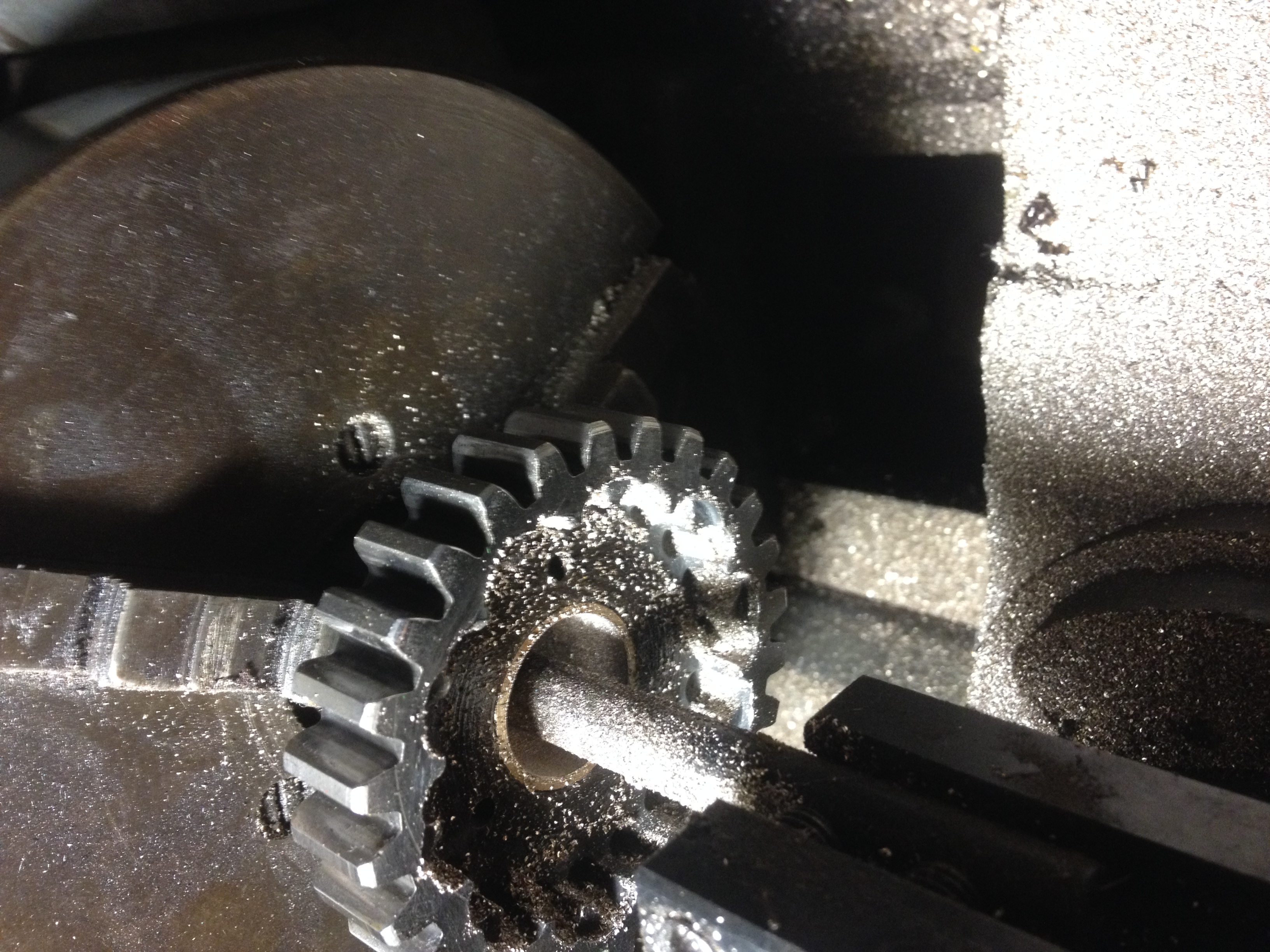
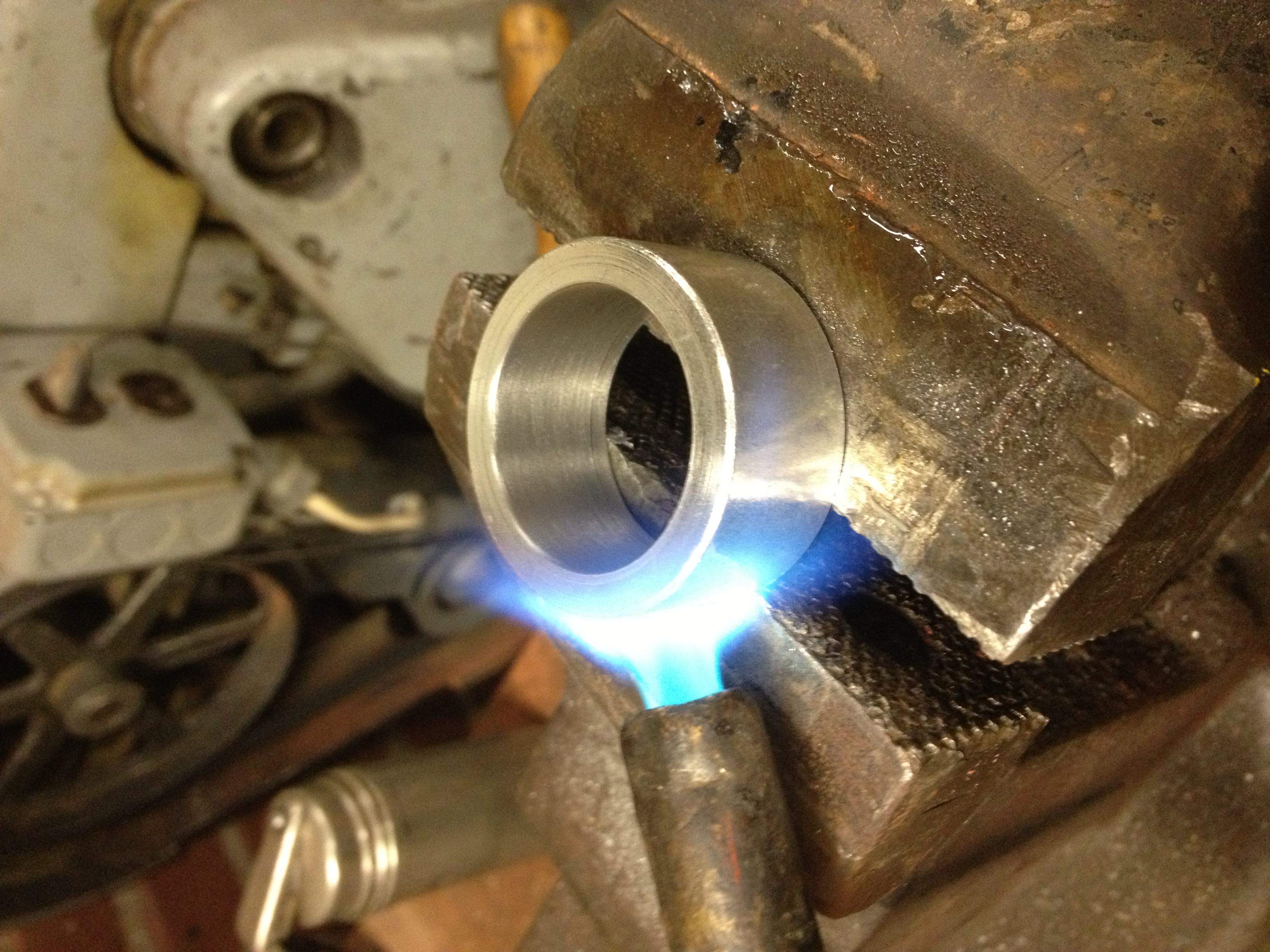
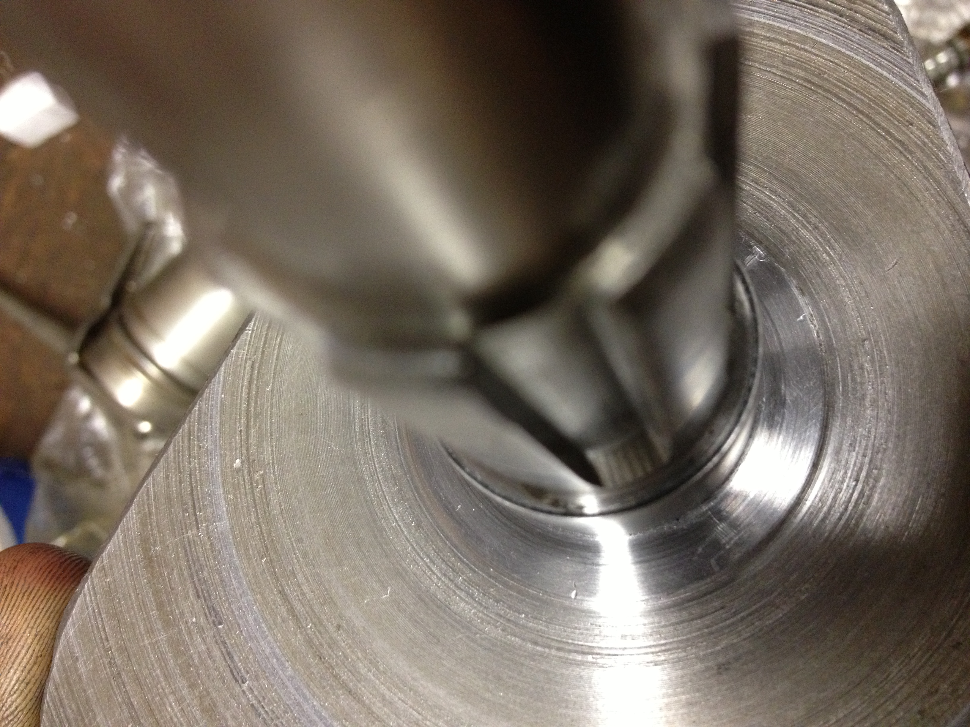
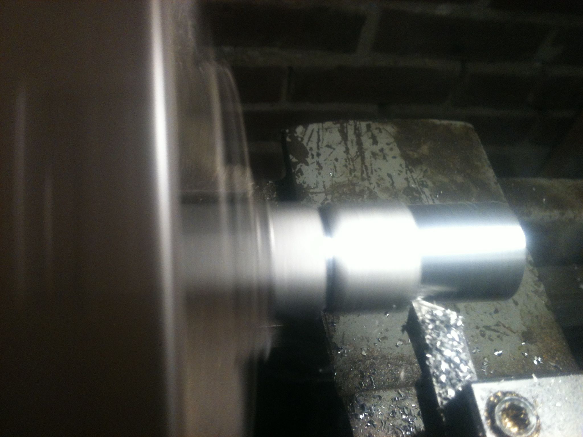
Boring the ID concentric to the bearing surface
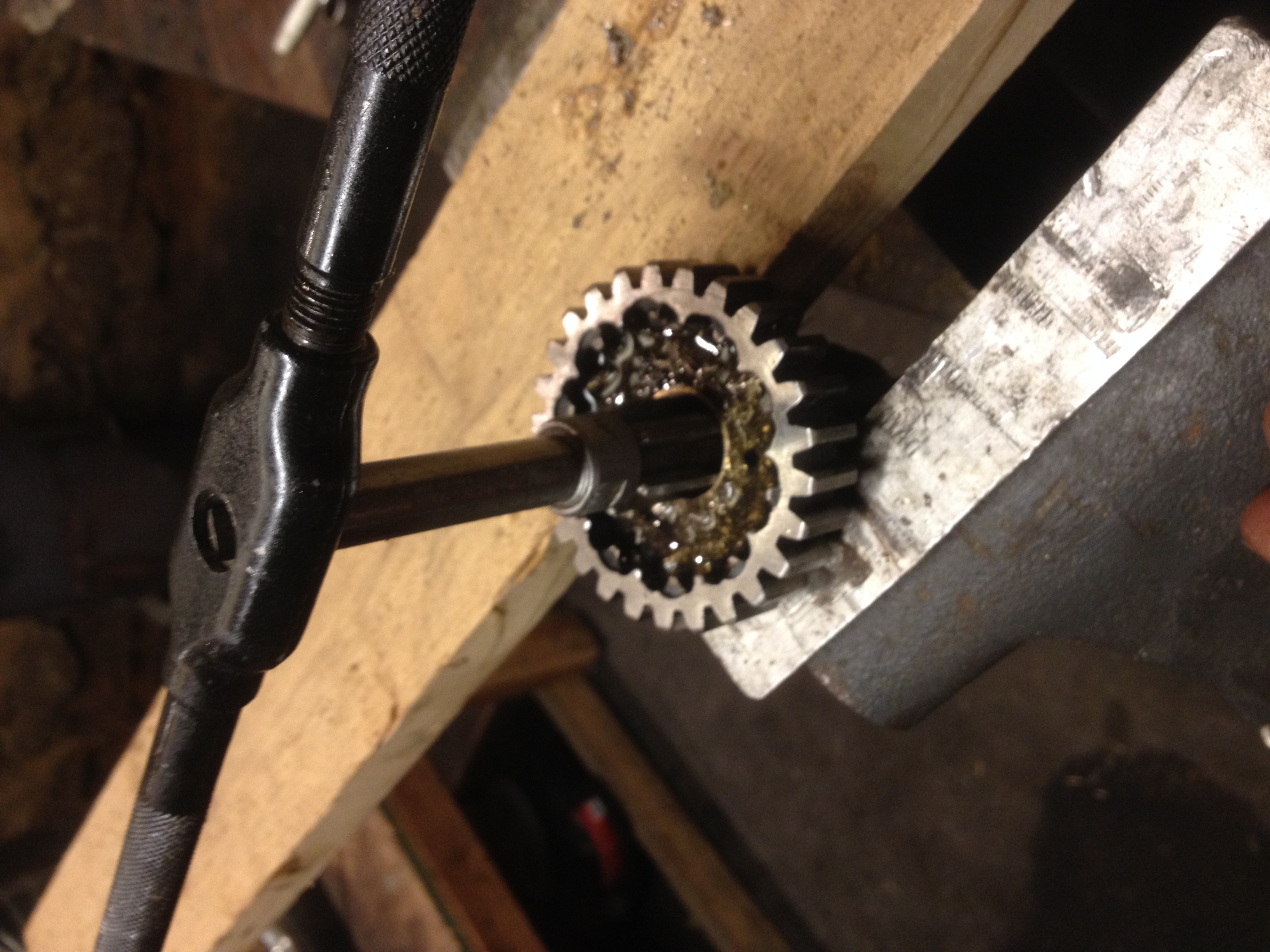
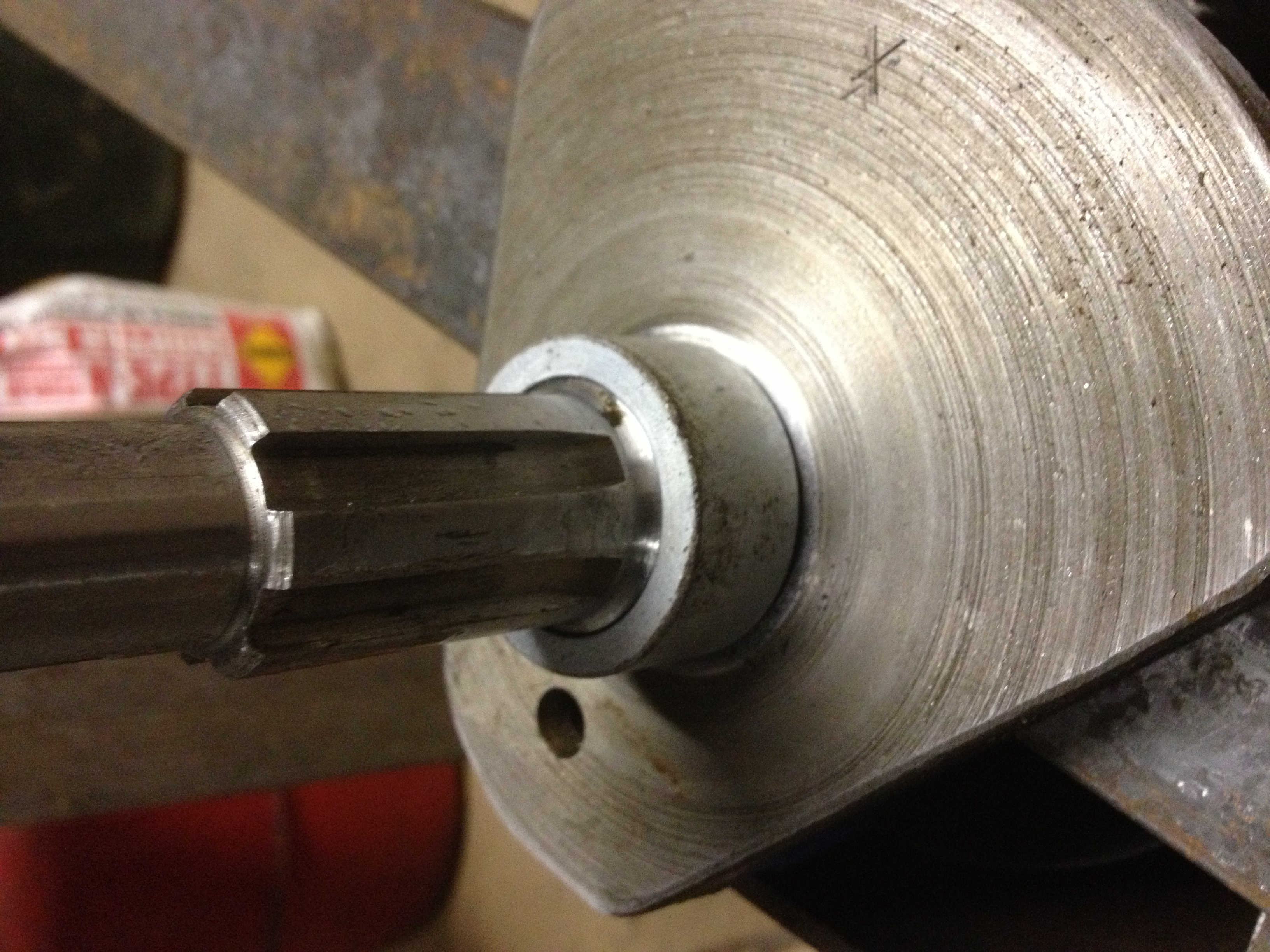
Reaming to fit the shaft, check fit often
Perfect fit!
Next week when I return from LA I will put it all back together and give it a test.
Dan


