4LS to Roadholder Fork (part 3)

Managed to squeeze in one more session last night before heading out for vacation in DR Friday in the wee hours. You know I’ll be thinking about this project next to the pool with a drink in my hand. Can’t turn it off. Ever.

I walked into the shop last night at 8:30p after a 15hr day traveling and working. I was on the lathe making chips by 8:33p.

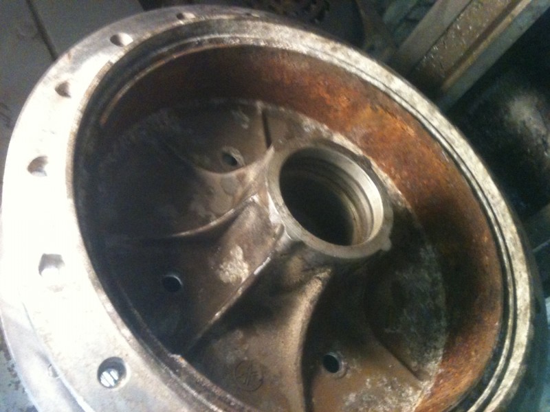
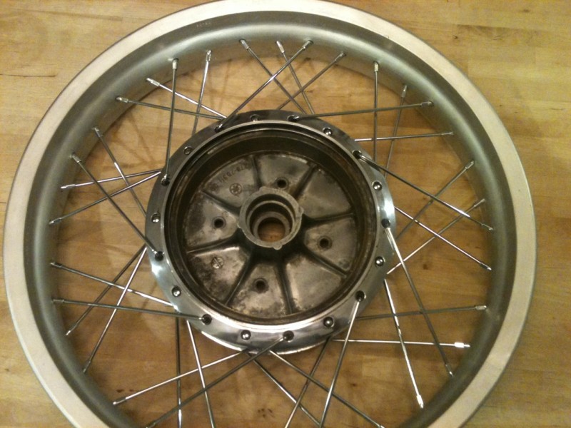
This is the original Suzuki axle that belongs to the hub/brake. Research showed that most folks used the Norton axle for this modification. Well, I don’t have one. Plus, the Suzuki axle already has the correct dimensions for the bearings, which is an important fit. At the end of last session, with Young Dan and Mika’s input, we came up with a plan to turn down the pinched section of the axle to match the right right fork leg. We also decided to bore and bush the left leg to match the smaller axle diameter and face it off so the brake plate and heavy washer and main nut will have a large uniform engagement area to better handle the increased braking loads and resist deformation.

I didn’t have a suitable piece of steel to make the bushing so I used a piece of bronze bushing stock I found in my scrap bin. I never throw metal away. I’m the type of weirdo that will pick nuts and washers up off the street and pocket them for later deposit in the junk barrel. Don’t laugh. I almost always come up with a suitable piece of material.

Step by step below in pics, as usual. Only had a cell phone last night, so pics are crappy.

Bonus question for the observant: One of the fork legs requires one more machining operation. Be the first to name it and we’ll send you sweatshirt next time we make a batch.

Adios, mi amigos.

Jason

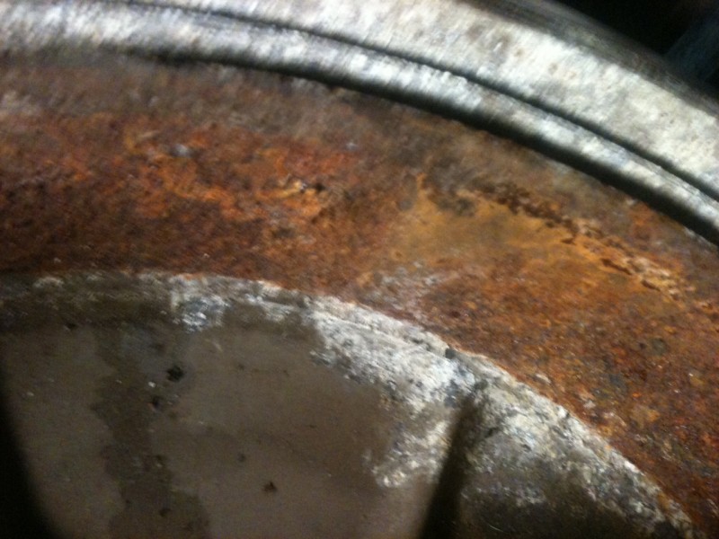
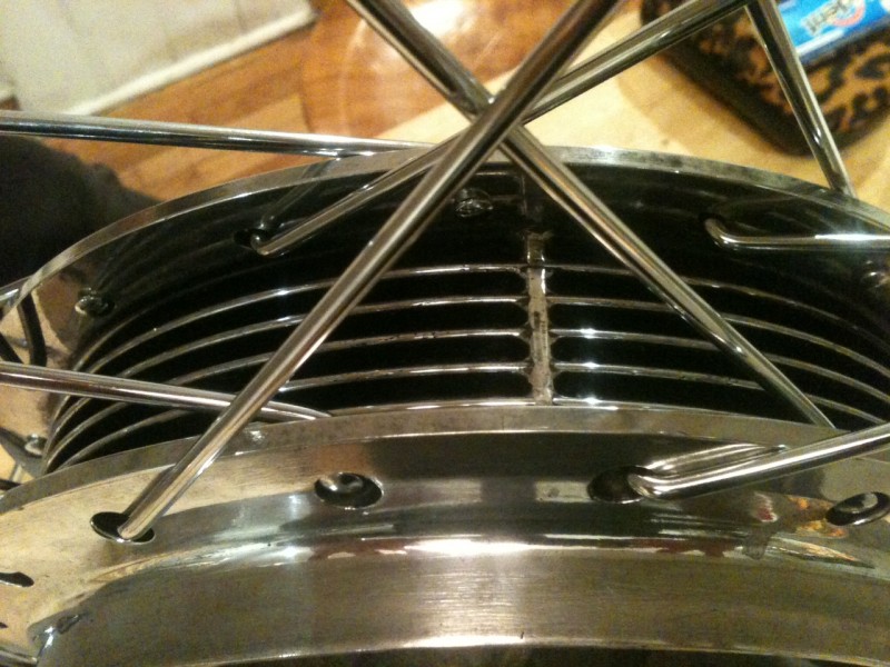
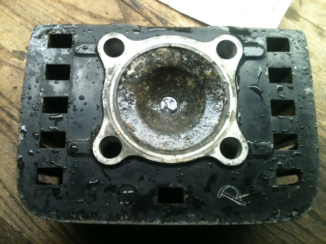
Pinch-side fork leg before modification. Note the crack. I don't think it's in a critical area considering most of the load is borne nearer the pinch boss.

Locating the fork leg in the milling table vise is a hassle and takes time to get right. I decided to try a new approach. I made an arbor/fixture out of aluminum such that one side fit the collet and the other a slip-fit in the fork axle boss. Chuck the arbor, install the fork leg and locate the table and vise to the suspended leg. Tighten down and check that the arbor travels freely when you raise and lower the quill. Worked like a charm! Had to set the leg three times last night for various steps and this took a minute each time.

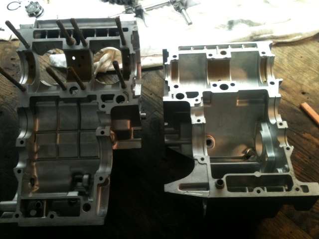
Suspended fork leg on the fixture/arbor made for this purpose.

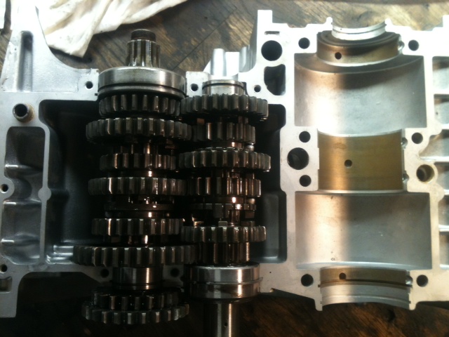
Boring the axle boss on the mill. This old girl is in such great shape the automatic down-feed and shut-off still work flawlessly. These features are usually broken on old manual mills. I wanted the bushing to have sufficient wall thickness to that it would not deform when pressed in. I also wanted a uniform hole for the press-fit. Otherwise I would not have modified the fork leg.


Continue reading

4LS to Roadholder Fork (part 2)

I’m on a roll here! Three shop sessions in a single week. Feast or famine.

I’ve been thinking this project over in my head every day and considering things I may have overlooked or misunderstood in earlier sessions. That’s the way I work. Constantly confirming observations and reassessing approach. I catch a lot of mistakes and omissions this way. Last night I tested a few initial assumptions with some layout blocks and squares. First, that the protrusion of the fork axle bosses was equal on both sides. It wasn’t. Second, that the hub and brake plates were symmetrical. They are despite different casting features on the speedo drive side. Lastly, that material must be removed symmetrically from fork leg pairs and brake plate pairs. Not true. An artificial constraint. Really, only the total amount of material removed the combination of brake plate and fork on each side must be same (less any symmetry difference in the legs) in order to leave the hub centered in the fork.

This last realization allowed me to save more material around the speedo drive boss and leave it in working condition. There was room to cut the fork back further on the speedo side allowing me to cut back less on the corresponding brake plate. An important finding.

So I got busy after getting home from NYC at 8pm. Getting up for work at 5:30a, traveling to the city to work all day, then driving back to Philadelphia makes for a long day. Didn’t stop me from heading directly to the shop though.

After removing another .110″ from the speedo-side fork leg, I next set about figuring a way to fixture the brake plates in the lathe or mill for final material removal. I preferred to use the lathe if possible as it’d be much easier to ensure the faced surface was perpendicular to the axis of the axle. There was no way to grip the brake plates with my 10″ swing lathe (due to no suitable protrusions, not diameter) so I decided to make an arbor out of some steel round stock, turned down to a press fit in the brake plate sleeve. This worked great. When done, I just pressed the arbor out on the hydraulic press. I also faced off the arbor so that I could use the depth mic to quickly and accurately measure material removed from the brake plates while still fixtured.

It all worked out and I got much more done than expected. The modifications are complete and the hub/brake setup slipped between the fork legs perfectly!

Next step is to modify the axle and fasteners to fit this Suzuki axle to the Norton fork. We came up with a plan late last night. Details in coming installments. After that, design and creation of brake stay straps and a fork brace to run between the fender bosses. Then finally, to polish and paint it all up for a proper appearance on JW’s fine Brit racer.

Jason

The mouting arbor pressed into place on the brake plate. Fit is .001" interference. The arbor is shouldered. The plate indicated true once mounted in the lathe chuck.

The machined arbor face used to measure material removed. Using a depth micrometer dropped from the boss (in red) a reading can be taken quickly and accurately.

Removing material on the lathe. Note the steel insert feature on the brake plate.


Continue reading

Using an EZ-Out and Properly Installing a Heli-Coil

Found myself with a free afternoon in the shop today and put some more time in on the Suzuki 4LS hub to Norton Roadholder fork conversion. After pulling all the parts out of the kerosene tank from soaking all week, I started to fix up the fork legs.

The one leg had a broken off stud in the fender mount boss that looked like it’d been there for a while. Rusted in pretty good and a nice jagged break indicating it took a lot of force to snap. Usually that means it’s stuck pretty good. The other leg had a brake stop boss that needed to come off. Got both done today but I’ll save the latter for another article. As the new setup will use these fender mount bosses as brake stay mounts, I thought setting them up for a larger stud (1/4″ – 20) and installing steel thread inserts would be wise.

This article will show you how to remove a broken fastener from a blind hole using what is commonly known as an “EZ-Out” or screw extractor. It will also show how to properly install a helical thread repair insert, or Heli-Coil which is the primary manufacturer of these style inserts. I used a milling machine to do the drilling and tapping for the thread repair, but this certainly isn’t necessary. Since I have one, I’m gonna use it where it helps me. You could just as easily do it with a hand drill in a vice (with a little care) or better yet, in a drill press. Drilling and tapping in a fixed setup like a drill press or milling machine ensures the holes are drilled square and the tap starts correctly.

I’ve heard plenty of people say that helical insert thread repairs are no good or don’t last. Bullshit. When installed correctly (I suspect many that say they don’t work are ham-fisters) they will be stronger and last longer than the original threads. Many manufacturing applications use them as standard equipment, not just for repairs but for new products.

There are sleeve style inserts for thread repairs too. They have strengths and weaknesses just like helical inserts. Some fixes may lend themselves to one or the other, but that’s a subject for another day. Both will perform beyond adequately when installed with care.

I had a great day listening to old blues and gospel music with the early spring sun shining in my workshop window. Just me and an interesting project. Hope you find this helpful.

Jason

The first step is to grind or file down the broken screw so you have a nice flat surface to start with. Be careful not to gouge up the surrounding area too much. After it's ground flat, you can center punch the broken screw so the drill will not skip off.

Carefully drill a hole in the center of the broken screw. The largest hole you can drill without going into the surrounding material is best. This serves two purposes: 1) Allows use of a larger screw extractor that can take more force 2) Thins the screw you're attempting to remove, exerting less force on the hole in which it's stuck.

After choosing the extractor that fits the hole you just drilled, place it in the hole and smack it forcefully with a hammer so that it bites into the screw. Be careful not to shift the extractor or put any lateral force on it after you've "set" it into the screw. You can see in the picture how the sharp edges on the extractor bite into the screw and are twisted counter-clockwise such that it grips better as it is turned outward.


Continue reading

4LS to Roadholder Fork (part 1)

My friend JW is building a traditional British cafe racer from parts he’s been collecting for some time. He has a Norton slimline featherbed frame, a Roadholder fork, and Ariel pre-unit motor and a beautiful hand-shaped aluminum tank. He suggested that documenting the conversion of a Suzuki 4LS brake (four leading shoe) to an early Brit fork might make for a good read. I agree. Let’s do it!

This hub and brake setup is pretty sought-after for its significant stopping power and that it’s not a modern disk. I think they’re worth upwards of a grand, so I’m measuring three times for every cut. Modification is necessary because this hub is over and inch-and-a-half wider than the forks it’s going be used with.

My plan is to remove material from both the brake plate axle supports and the inside fork bosses to make it fit. The original brake stay boss needs to be removed from the fork leg and straps will have to be made to anchor the brake plates to the fender mount bosses on the fork legs. The speedo drive mechanism and associated features on the brake plate will have to be removed and welded in. A new axle will also have to be made once I get the hub fitted up nicely. I’ve decided to no attempt any lightening of this brake/hub (it’s HEAVY) as I don’t really see any opportunity for significant lightening. The internal aluminum webbing could be drilled but how much weight would a few slugs of aluminum save when compared to the four thick iron liners and various steel linkage parts? Not worth it to me. For now, JW agrees. But he’s one to tinker (and do it well) so we’ll see what he does with it after I give it back to him.

First order of business last night was to measure the fork and hub to get the final numbers for use in trimming down this hub.

Using layout dye on my metal bench top to measure the width of the fork at the bosses.

Using a square to ensure leg bosses are perpendicular to the table surface. I then scribed the table at the back of the square on each side and measured the distance between the marks.

The final numbers tell the tale. Having a metal bench top is great for notes and measurements.


Continue reading

Drum Brake Redux

For one reason or another I am always fixing the crappiest, clapped out parts, Partly because I’ve sold all the good ones or I’m broke when it comes to buying motorcycle parts and have the tools to fix them. This drum brake hub was no different. The rim and spokes went to the scrap yard.

Chucked in the lathe ready to take a cut on the braking surface.


Close up of the severe rusting

Any time I have a wheel apart like this I like to resurface the drum because there is no other way to do it. This particular hub is made of aluminum with a cast iron ring pressed into it for the shoes to ride on. Years of sitting have severely rusted the cast iron part and corroded the aluminum. After taking about .020 off the surface it was looking like something useable again and a  final cut made it workable again.

After the cuts and cleaning

Spent the next few hours polishing and painting the hub before lacing it to a new SUN rim. There is a lot of info on building wheels on the net but the one I prefer is by a guy named “Sheldon Wheels Brown” He builds bicycle wheels but his info is superior to all else. Find him here. A few things to watch out for, Motorcycle wheels often have different length spokes and cross patterns in the same wheel. Meaning you can have up to 4 different spokes per wheel. This wheels spokes were the same length but the inners and outers had different lengths from the elbow to the butt end. You should try building your own wheels some time it’s fun and easy.

Looking fine

Happy New Year!
-Dan

RD motor build

Went down to the shop on christmas day eve for some motor building fun. I have been collecting the parts and I needed over the last few weeks. Here it is to enjoy

Cases back and bare from getting the "treatment"

Trans in and endplays checked and set

Clutch side

Bearings on crank and seals installed

All together now

Removing A broken bolt

If you turn a wrench on an old bike for more than 5 min you bound to find a broken bolt, stripped threads, or rounded fasteners. We’ll be removing a broken spark plug from a head. A few of the things working against us here are: Dissimiler metal corrosion with the plug being steel and the head aluminum,the fact that this head hasn’t been on a running bike since 81′  and was sitting in upstate ny it’s whole life.

As you know my cases and heads are out in Oregon getting vapor blasted. Guy sent me some pics and they look great. Bad thing is the $6.50/hr truck unloader at fedex doesn’t give a shit about my parts and they arrived In Oregon with a broken fin. I had an extra head but it still had this broken plug in it and I had tried simpler methods of removing it weeks before to no avail.

Theres lots of ways to remove a broken bolt, but my favorite is to weld a new bolt to it to allow use of a socket and the bonus of this method is the added heat cycling from the welding itself. First I drilled the old plug out to the same size as a junk bolt I had, this case it was 3/8. This allowed me to put the bolt in and get a good weld on the freshly drilled metal.

Underside of head with bolt welded to offending plug

Top of new "spark plug remover tool"

At This point I heat cycled the head a few more times with a propane torch for extra piece of mind and went ahead with the removing. As you can see It came right out first try.

Plug remover with the threads of the old plug visible on the end

I was  pretty pleased that it came out easily without damaging the threads badly. Since my tap and die selection is pretty weak right now and I didn’t have the correct plug thread tap I did the next best thing. This works especially well for the CEI and WHITWORTH fasteners because I don’t have ANY of those taps. I found an old spark plug and coated the threads with valve lapping compound. Slowly I threaded the plug in by hand working it in and out. Removing all the crud and corrosion out of the threads from 30 years of sitting. Plug now goes in and out freely.

All that's needed for the trick

If you are ever in going to get some Vapor Blasting done. I HIGHLY recommend Jeff. First class dude

Truing The RD Crank

By now Im sure all of you are banshee and Rd built up crank experts. This week we will be truing the crank. With the assembly being built up of 6 parts there are plenty of places for it to be out. The spec we will be shooting for is .02mm or .000787 in, thats seven hundred eighty seven ten thousandths. There are three places to check this “trueness”, on the two ends of the crank and in the center bearings. If you paid someone to do this this is where money all went. We will support the crank on the center bearings and take our measurements with a .0005 dial indicator mounted on a magnetic base.First we set the crank on the V block and spin it through supporting the rods and making sure there are no hang ups. After you establish that you spinning free its time to put the indicator on it and establish a baseline as to where its out . As you can see from the drawing below there are 4 planes we are checking in. We’ll call the crankpin 0 then 90 degrees going around the crank, 180, and 270 respectively. Rotate the crank checking all these and see the chart as to where you should hit to correct it. Don’t be shy at first, my crank was over .040 out when I started and it took a good while to get my arm calibrated on how hard to hit it. Check all points after each time you adjust he alignment. As you get close you will want ease up and just lightly tap it to bring it home. It took me about 45 min to get it within .001 and an additional 30 min to get it to .0005 where I left it. Well within spec and at this point Don’t breathe around it as you might just throw it off a few 10 thousandths. -DAN

Square pegs in round holes

Just when I was about to button up the ’64 panhead last week after rewiring and a bunch of other improvements I found the seat pivot boss to be stripped. Dammit. Decided to go to 3/8″ bolt from 5/16 as the tab is not really thick enough for a thread repair and tapping welded areas varies from troublesome to impossible. The original pivot pin is hardened and ground and made out of that incredibly tough metal that Harley used to employ as a matter of course. Carbide wouldn’t put a scratch in it. No way to bore out the original pin.

So I made one out of 660 bronze. Sorry once again, purists. Functional over stock every time, where the latter isn’t available and I’d like to actually ride somewhere.

So the only bronze stock I have is square. No way to hold it in the three-jaw chuck on the lathe. Guess I’ll break out the four-jaw. It’d been a while. Then I figured I take a couple snaps and show how to center a part in the four-jaw chuck. Here it is. . .

A three-jaw chuck is designed to close concentrically on any round or six-sided piece with a single adjuster screw. It is the type most commonly found on lathes and has a million uses. Sometimes though, you have do do offset or square work. The four-jaw chuck has four independently controlled jaws that must each be set when aligning a part as desired.

Here is a chuck I got pretty cheap and rebuilt it. It's been around the block a few times, but who hasn't?

The first step is loosely place your piece in the chuck and get it visually centered by whatever means you like. You can eyeball it, rotate it by hand slowly, use the guide lines on the chuck face or anything else you can come up with. Once the piece is where you like it, snug each jaw, but not too tight as you’ll be making further adjustments.

Square bar loosely in chuck.


Continue reading

We Fix Our Own

Vinny paid a well-known shop to weld up and rethread the spark plug bosses in this set of early shovelheads. When he got them back they looked like they had been cut with a dull chisel. Worse yet, the spark plugs no longer reached into the combustion chamber because the shop didn’t machine them down enough.

Why deal with idiots twice? We fixed it.

His first time on the Bport. We’re so proud!

Jason

Set the controls for the heart of the sun. (Be careful with that axe?)