Rd350 built up crank assembly

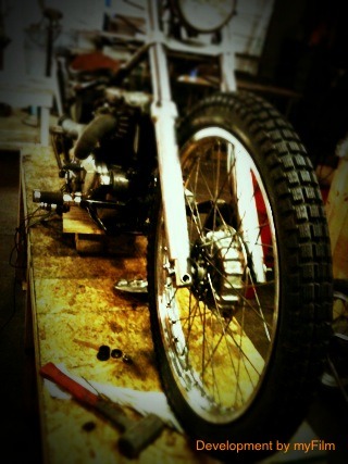
A few of you may of seen the pair of RD350’s I picked up a few weeks ago and there subsequent tear down. This will document the rebuild of the crankshaft. As I type the cases are out in Oregon being vapor blasted HERE, a process similar to glass beading except that its done with a slurry and produces a superior finish that doesn’t stain as easily and looks like the day the part was cast. In the meantime I have been sussing out different things on the bike and gearbox, removing unesscary tabs on the frame and collecting parts for the rebuild.

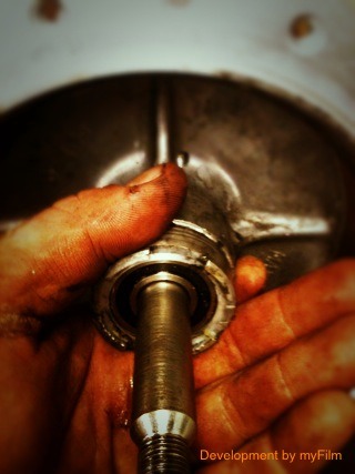
Having dissembled the the crank to inspect,I found out I would need new connecting rods and bearings in addition to the 4 main bearings that support the crank.

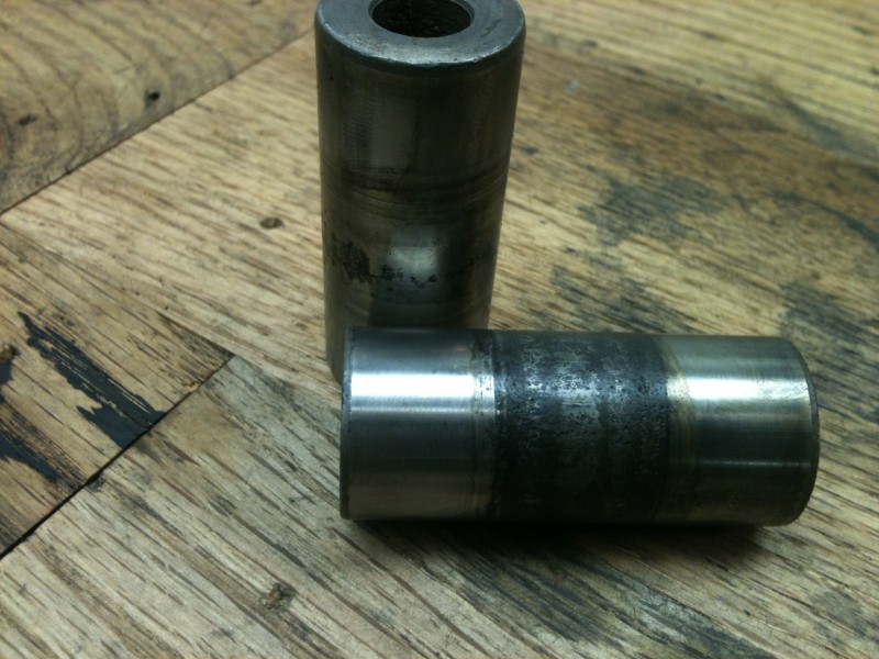
CRANKPINS, the big ends of the rods were just as trashed as well as some bluing form heat


While I neglected to take photos of pressing the crank apart it is almost the same as reassembly.

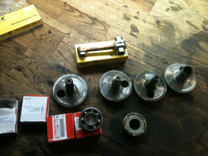
All apart with the pieces that will make it new again, also note the slotted con rod for better oiling

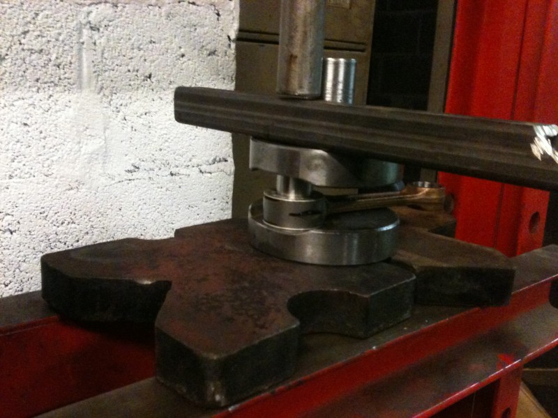
objectives are: Make special fixture to support the crank while pressing it apart and not bend the rods.

Almost fold the press and or explode my push bar to sepiarate the center webs that have been married for 40 years.

Catch crank halves as they fire out the bottom of the press.

All this has been accomplished by the simple fixture I made out of some large square tube with a half a dozen rags stuffed in the end and a plate with an notch cut out for the crank pin to sit.Crank pin in, rod and bearings and thrust washers on

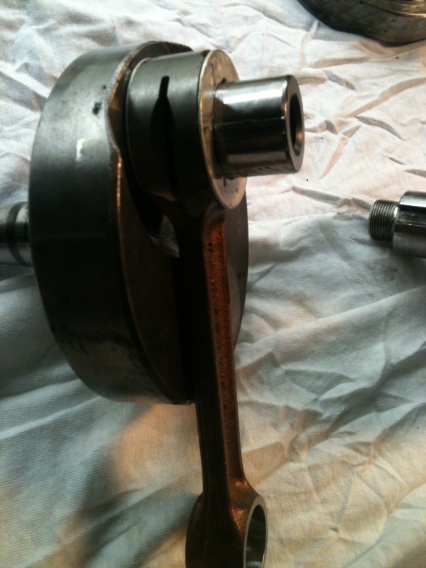
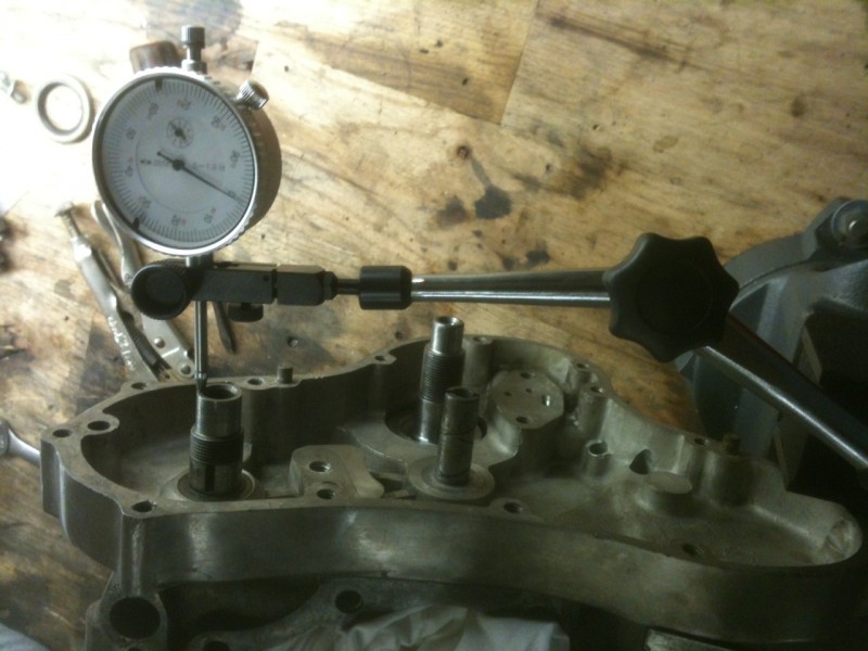
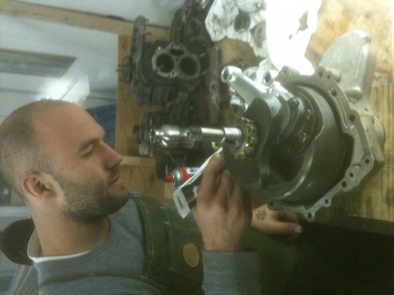
The most difficult part of reassembly is pressing the two sub-assembles together while maintaining the rod side clearance at .001-.003 You can’t see from the pictures how I accomplished this with two pieces of bar between the crank webs. This proved difficult as the clearance I wanted to maintain went away to almost nothing, at least it prevented me from bending the crank pins! Because of this I had to reset the side clearances, not  big deal but a little harder than while it was still the sub-assemblys.  This is the point where I began to get frustrated and stopped with the photography class. After a bit more futzing around I was left with an assembled crank. Next installment will be truing the crank, STAY TUNED!

Chris’s Norton mill goes together

Sunday night I met Chris aka Goodwill down at the shop to put his Norton Commando motor together. While he has never built a motor before he has a pretty good mechanical knowledge and I get the pleasure of working with him 5 days a week to answer all his questions. He’s been coming down to the shop on Sundays and tuesdays for a few months quietly working away. Ive been pretty busy with my other projects so I haven’t been paying much attention to what he’s been doing. All his busy work of cleaning bolts, fixing threads, and sorting what goes where paid off on sunday.

He will be running one of those fancy superblend bearings on the drive side an a ball on the timing side to control the crank end float.

Chris heating up the cases to accept the bearing race

Crank has been built up and the rods polished by Classic Cycles in frenchtown NJ, you could comb you beard in the reflection of these things. We put the bearing in the “bearing shrinker” aka shop fridge for a while and sorted a few things out. After sufficient shrinking time Chris fired up the heat gun and heated the cases to install the bearing. It dropped in for install with no hamfistery needed.After that, we used sufficient force to assemble the case halves for a dry run on the end float of the crank and camshaft. 2 or 3 tries later we had the float within acceptable limits on both and were ready to jizz them together.We fitted the halves back together one last time and torqued the bolts to: just tight enough in/lbs, checked it one more time and had a Beer. PERFECT SUNDAY


Synching Twin Carbs

We were talking with a friend last night who was trying to get his dual Dell’Orto carbed Guzzi synched and idle speed set. As is often easy to do, we slipped into over-analyzing what needs to be done and how to accomplish it. Then after a a couple beer’s worth of continued speculation and jabber, we reeled it in and simplified it.

Synching a twin is easy. Here’s how to do it.

Some people are conceptual learners, needing to understand how something works and the approach behind tuning it. Others a procedural learners, concerned more with how something is done than why it works. Both are valid. I’m in the former camp. I’ve found that once you know how something works there are many different recipes for how to do it.

There is only one goal in synching your carbs: To have all cylinders contributing the same amount of effort at any time.

There are three steps to doing this on your twin:

1) Obtaining the optimal idle fuel mixture for both carbs

2) Setting the idle speed screws so both carbs run at the same rpms when the other cylinder is not firing

3) Adjusting the throttle cables so that the throttles move at the exact same time when the grip is turned.

There are some tools you can use to make this job easier or quicker, but they are not required. You can do a fine job of synching with just your ears and a screwdriver. A simple vacuum gauge like one you’d get at the auto parts store will make setting idle fuel mix easier. A motorcycle carb synch tool makes step one and two easier. A tachometer could also be used in place of a vacuum gauge or synch tool for the first two steps.

Continue reading

Early HD Timer Conversion

Where can I buy one of these? Nowhere? Ok.

We’ve been helping Ralph turn his ’70 XLCH (The Iron Headache) into a reliable machine for regular use over the last couple months. As most people who’ve owned an ironhead will tell you, there’s a pile of work hiding in all of them. Some choose to refine the bike over a period of years fixing crap as it occurs. This gets tiring and often leaves you short of your destination. Some folks like that approach and that’s perfectly valid. We’re trying fast-track Ralph to understanding his machine thoroughly and addressing all the major systems in advance of their likely failure. This week? A non-fidgety low maintenance ignition system.

His bike has an external ignition timer as opposed to the embedded timing chamber that later sportsters and cone shovels have. This slims down the choices a bit. There are three main issues that limit choices: The timer does not accept a bolt-in points replacement as the body of the timer itself carries the points. The timing weights are also integral with the timer shaft preventing use of an ignition that doesn’t use centrifugal advance weights. Lastly, the timer shaft rotates clockwise whereas later sportsters, cone shovels and evos rotate the timer shaft/cam counter-clockwise. Hmmm.

I recommended a Dyna S for this job, as would probably anyone who has put serious miles on an early bike. They are cheap, simple and stone reliable. There’s a reason most bikes at the drag strip run them. You can run them with stock HD coils and existing weights. In the even of a rare failure out on the road, you can pop your points (that you carry in your tool bag, right?) back in and keep it moving.

Young Dan and I got to figuring out our approach last evening using an old Dyna S I had in my stash. We had it largely figured by time Ralph arrived. Both of us are prone to impatience and are easily consumed by interesting problems to solve. Details are in the captions below. Enjoy.

Jason

We removed the pickup sensor from the new ignition and marked holes for mounting on the old timer. Tapped to 4-40 to use the mount screws it came with.

Continue reading

They Stopped Making These . . .

Hmmmm. How to make this part fit that part. . . I don’t think smashing it closed and bolting it down will do.

So as I’m leaving to go for a ride a couple weeks ago the kicker on the red & black pan gets stuck in the bottom position and no longer turns the motor. There were no noises or other indications that the shaft had broken, but it did. A number of years ago I fixed this shaft when the threaded boss for the internal gear sheared off. That one was my fault. Sometimes I’m still a gorillla-fist and tighten things too much. I machined off the end and tapped it for a retainer screw and made a thick retainer washer. This fix lasted about five years. Not bad.

At that time I was too stubborn to buy a new shaft as I thought they were too expensive at almost a $100. Well, now you can’t get one at all for any price. I searched pretty thoroughly. Seems they stopped making them. The shaft for this particular kicker has an oversized boss where the arm attaches for increased strength. The arm has an extended length compared to stock, too. The attachment point on this one measures at .788″ where a stock one is closer to .600″. That’s a big difference to cover by fashioning some kind of shims but I imagine it could be done.

I ordered a replacement shaft of stock dimension from the local shop (Riverside Cycles in Phila) and figured I’d come up with an idea for how to make it work shortly. It came to me later that day: Cut the old shaft in two, keeping the oversize arm attachment portion. Cut a perfectly good brand new shaft in two, keeping the internal gear and shaft portion. Weld them together. What makes this job tricky is that the shaft material is extremely hard, tempered and precision ground. You can’t weld at the shaft as you’d have no way to grind it back down to original dims. It’d also probably be weak. I decided to cut them off just behind the arm attachment point, taper them down to a “V” shape to allow deep welds and then clean up the welds back to original size.

Guess there’s no way you can claim to know how to weld if you don’t trust your own work. This application will be good test. You can imagine that there are major forces exerted at the repair point including flex and torsion. I don’t claim to be a welder but I have welded a ton of parts for my bikes and a few others’ that have held up just fine. I know the machine I have very well and can generally be confident in my work. I also have fucked up a bunch of stuff. . . and like to think I learned from it. We’ll see with this one.

I was pleased with how this came out in that at least it looks decent enough. I’ll see if it holds in real life. This kicker is used to start a 93ci shovel/panhead motor with 9:1 compression. Not huge, but no 350 Honda either. I’ll keep you posted.

Let’s get to it. Pics and steps after the jump . . .

Continue reading

PHOTO ESSAY: fitting a 23″ wheel to a late sportster front end

This serves to test out posting through an outside source AND how I fitted a 23″ xr500 wheel to late sportster forks


Wheel as delivered


Cutting the axle to fit the new bearings


Oversized bearings from mcmaster installed and axle fitted


Relaced and trued to less than .020 out of round. Rim polished on the buffer


Brake backing plate all polished up with brackets to adapt to late forks and built in cable adjuster

Tuesday Shop Night

Shop night last night, like most Tuesdays. Don’t know how we picked that one, but it’s been working so why mess with it. The excitement and building momentum at the shop is in the air and we can all feel it. With the cold air comes a renewed interest in spending time building new projects and fixing the place up. Without formal planning of any sort, there were six people last night working on bikes. Perfect.

I got the milling machine variable speed conversion done last weekend and was ready to square up the head. I’ve not used this machine in two or three years and have moved it twice in that time. Young Dan and I and set about getting it trued up so we could cut something.

First we indicated a precision square on the table parallel with the Y axis and locked it down. We then traveled the head and made sure it was parallel to the reference square. Close enough.

Square indicated on table

Next we rigged up bent piece of round stock to check the nod and tilt. Took us about a half hour or so as I’m a little rusty and this machine was WAY out. After messing with it a while I remembered to set it up by eye first with the precision square then use the indicator for fine tuning. Done. +- .0005 all the way around. Lock it down and leave it. Everyone instructed to never move the head. That’s why we have a big adjustable angle plate (that weighs fifty pounds!).

Good all the way around

“Hey Dan, wanna cut something?”

Continue reading