
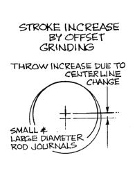
Most of you that know me know I have slowly been putting a Land speed bike together for the last few years. One of the only major things left to do on it was build the motor. I had been putting this off for a while for any number of financial reasons, (racing is expensive!) and collecting parts when they popped up for not two many clams. This is no ordinary call you local supplier and buy the parts then assemble job. Almost all internal parts need some kind of fitment and machining to work in harmony at 7500 rpm. A brief description of the internals would be 51 BSA A7 500CC cases to fit into the vintage class, I am using a late model A65 bsa crank for its increased journal size for added strength over the stock unit. Its a great idea except it shares almost nothing in common with the early one it will replace, furthermore class rules dictate you can not change the stroke of the motor. Stock small journal crank has a 72.4m stroke and the replacement has a 74mm stroke. Hmmm, this required a rather expensive offset grind to the main journals to reduce the stroke to the stock A7 throw. The BSA has a bushing on the timing side instead of a ball or roller bearing, this needed to be ground down as well to fit the STD bsa case.
The most dreaded part of this all is a bearing adapter needed to be made to mate the drive side bearing to the crank as the A7’s has a larger ID than the A65’s. I ordered a piece of steel from mcmaster in the approximate ID to use for this.
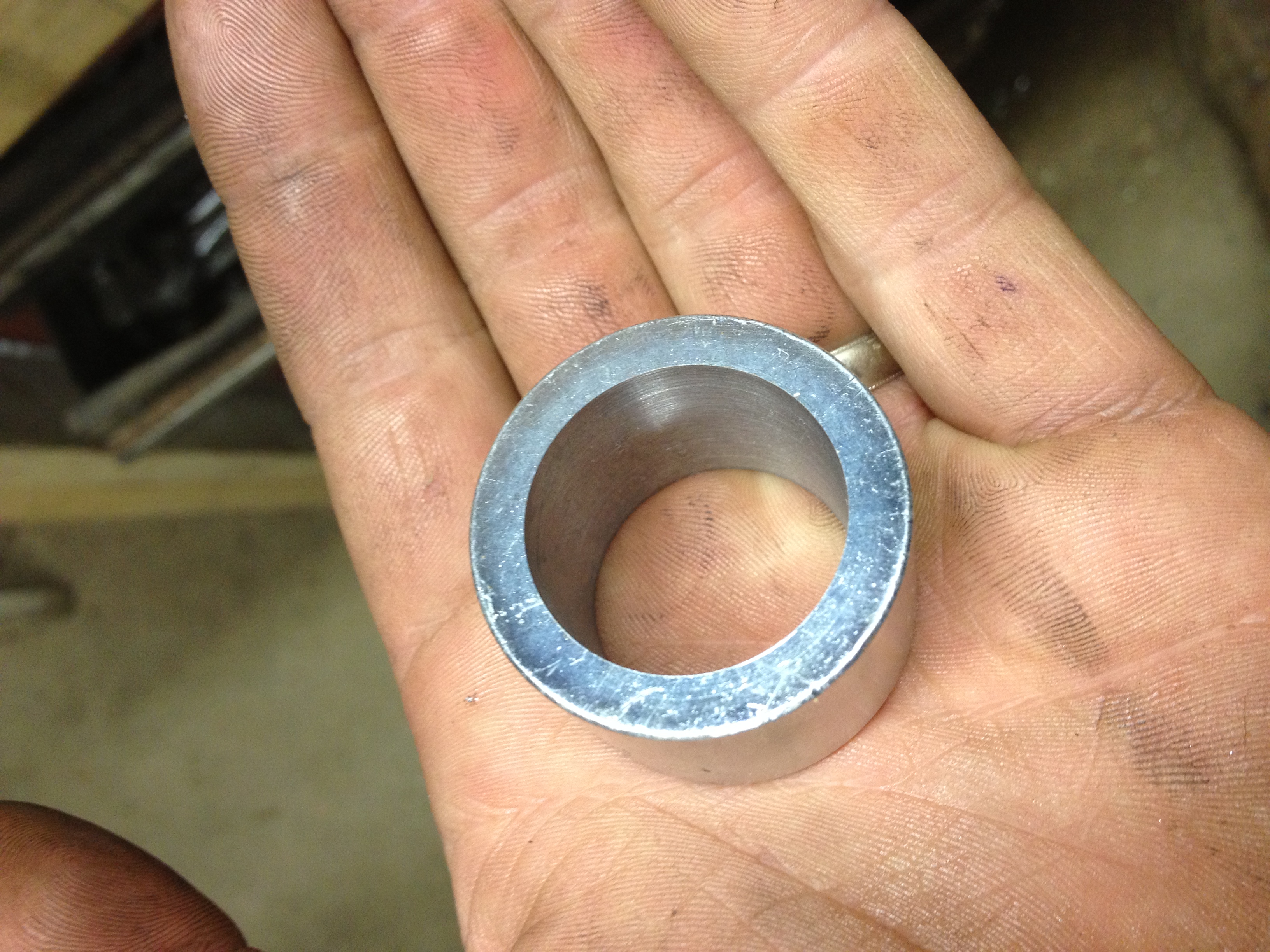
Bushing with the ID bored to size
This was by far the most difficult machinist operation I have performed not because it was complex in steps but the tolerences I was working in were in the .001 range, going to be subjected to high load and my machining equipment is 75 years old.
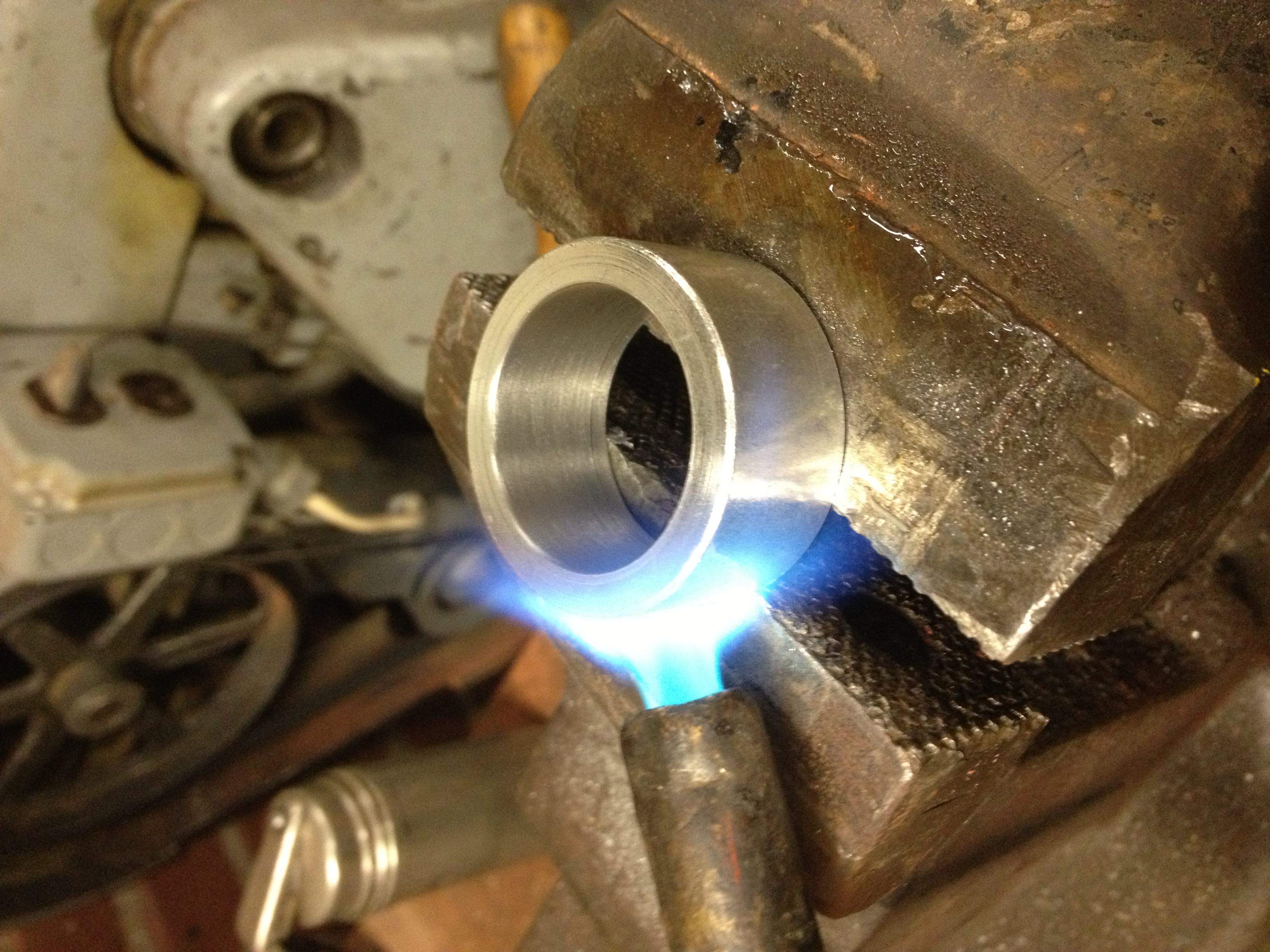
After boring the ID to size the bushing was heated to expand it before fitting on the crank
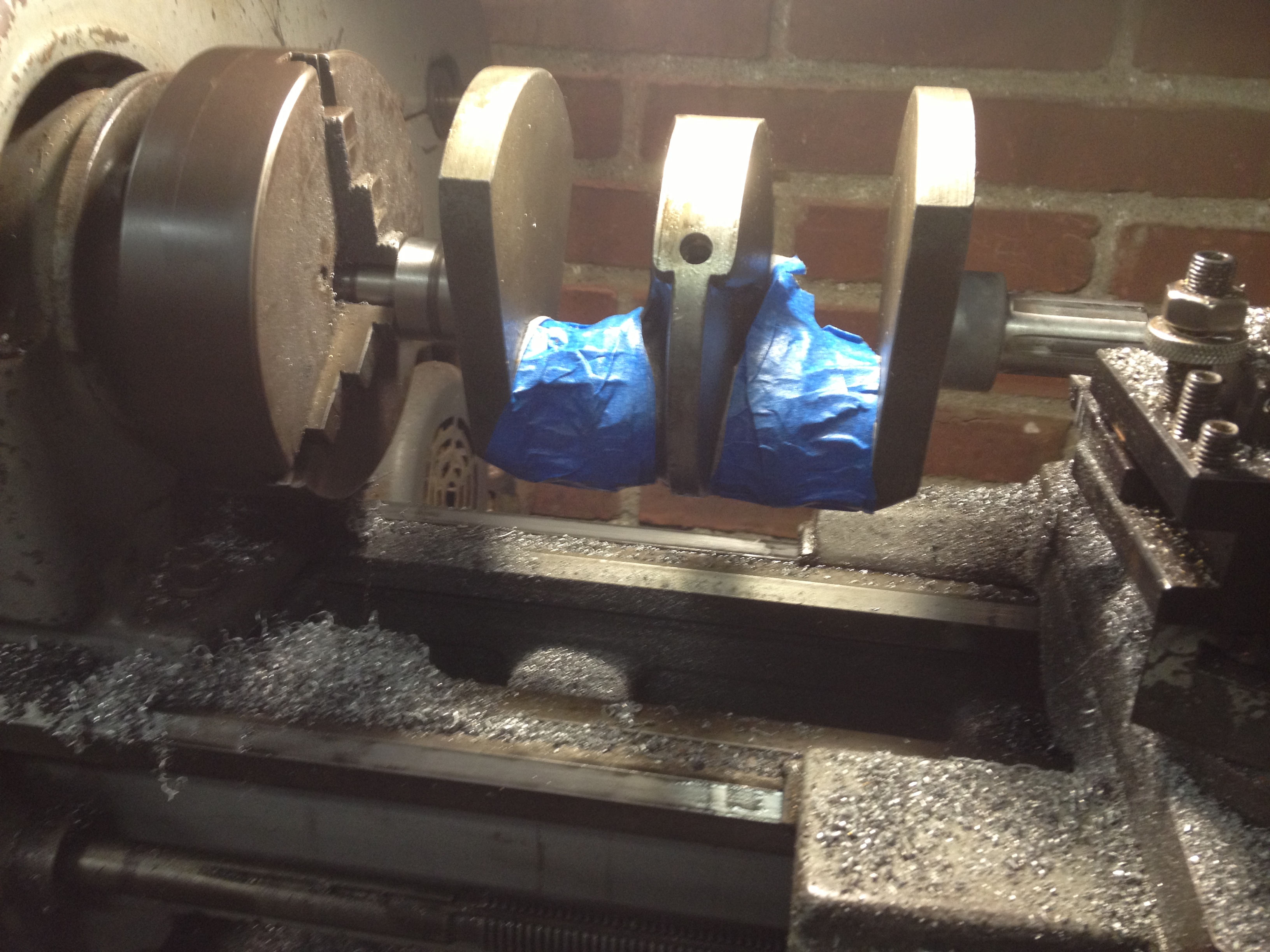
Before starting all this I put the crank in the freezer to shrink it down for the new adapter
Bushing on, with the differences in temp it just dropped right on
With all this done I had to machine about .300 off the OD to fit the bearing on. This was no easy task with the weight of the crank throws, it was descry to turn this at very low speed on a dead center. Using a carbide cutter does not give you a nice cut at this speed.
I made many cuts and stopped at .007 to big. I’ve been know to overshoot these things by a mile so it was time to make less aggressive cuts
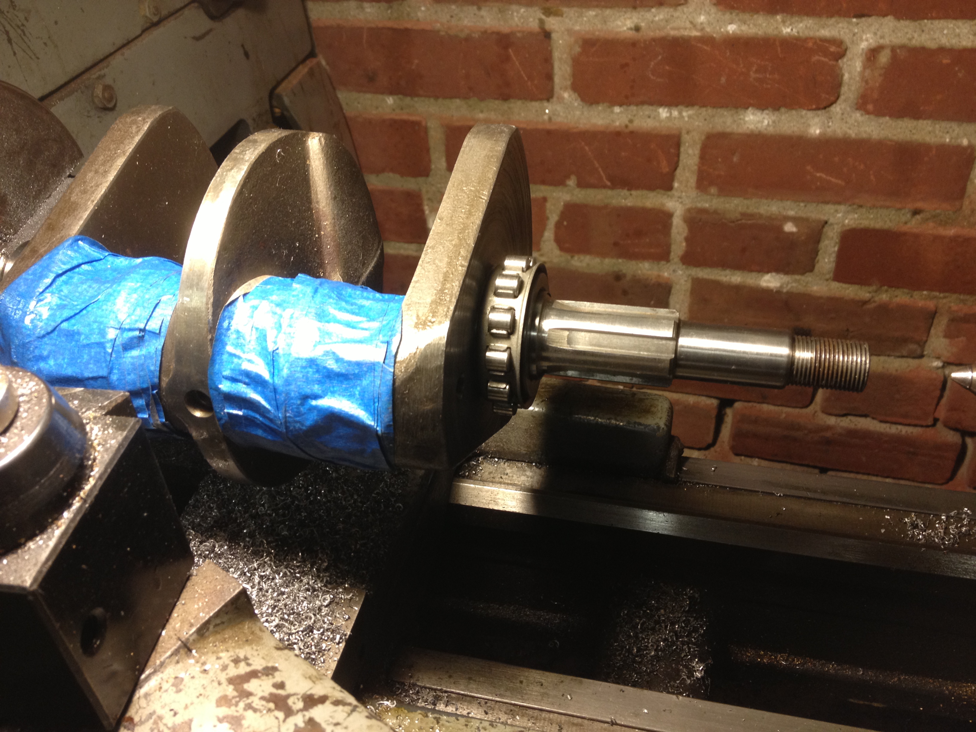
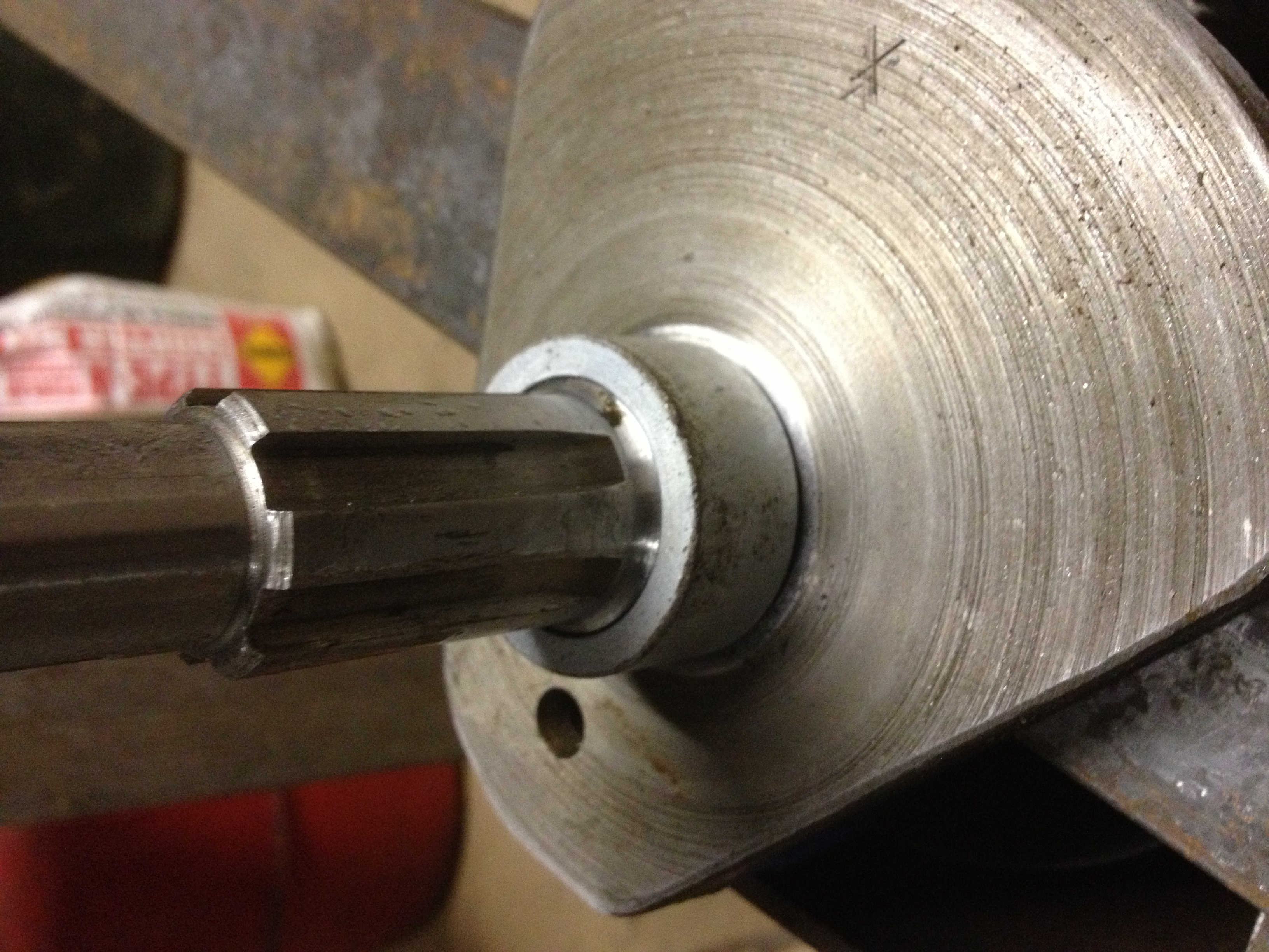
Bearing installed in new adapter
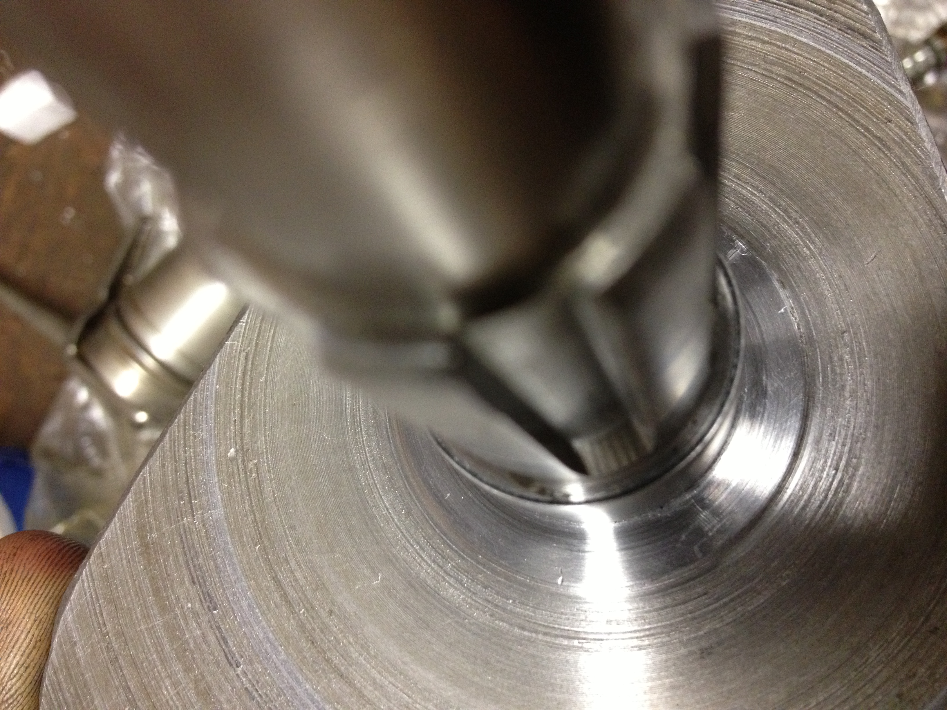
Here you can see the thinness of the adapter, its about .012 the final .007 was sanded down to fit the bearing. It took a long time and I checked the fit often
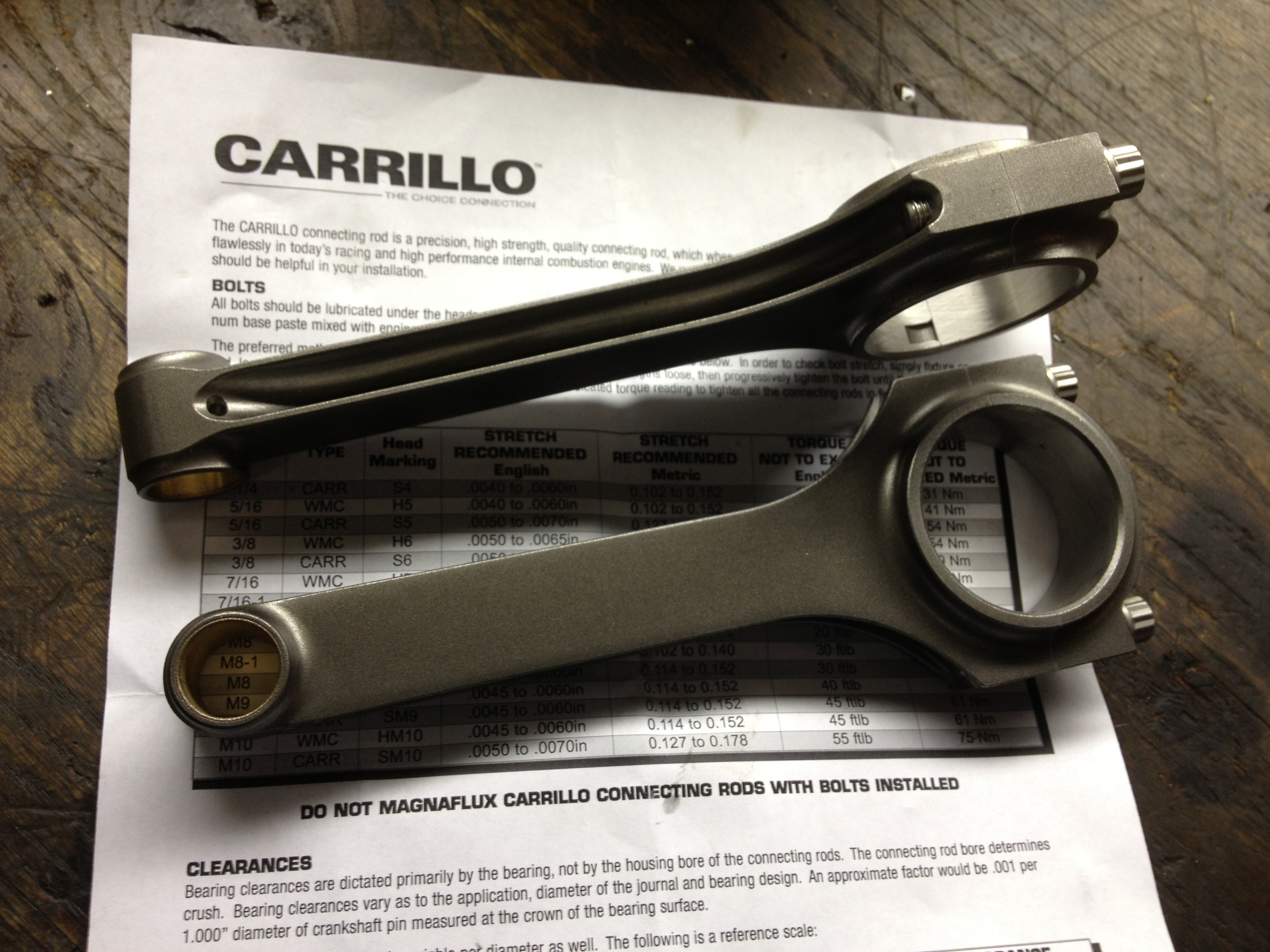
Carrillo H beam rods ready to be installed
I can’t tell you the feeling of accomplishment when the new bearing and adapter just dropped right in!
Stay tuned for part 2 and some work on the RODS