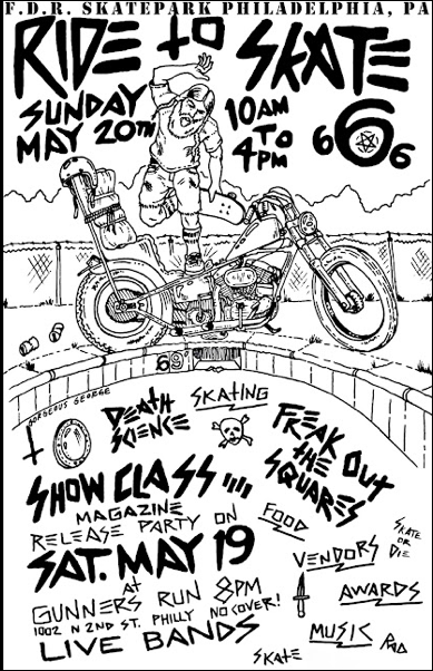
Our crew headed down to Joe’s Ride-to-Skate this Sunday at FDR skate park in south Philly.
We brought the north-side flavor. Tough as nails. Hardcore.

Wouldn’t have it any other way.
Our crew headed down to Joe’s Ride-to-Skate this Sunday at FDR skate park in south Philly.
We brought the north-side flavor. Tough as nails. Hardcore.
Wouldn’t have it any other way.
A few days ago Denny from california called me to bounce ideas about his current pan project. He has these flanders risers that he wants to fit to an early springer. Normally the springer top clamp has two ears that you would put dog bone risers on. He told me V-Twin used to make sell this but has called around and no one has had this for years. After 20 questions and some pictures I decided to turn these up for him.
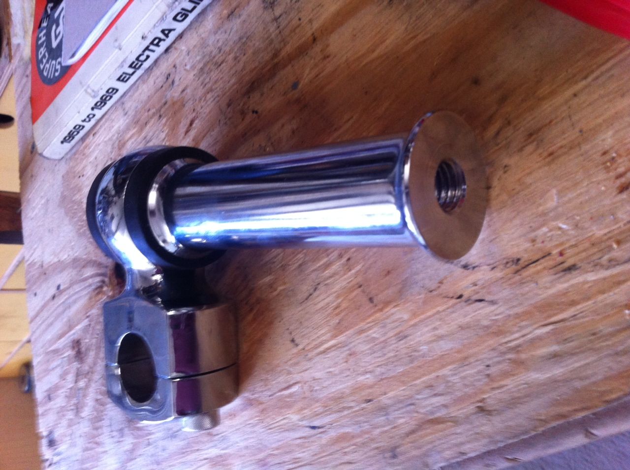
These are the risers, the bottom is threaded 1/2 x 13
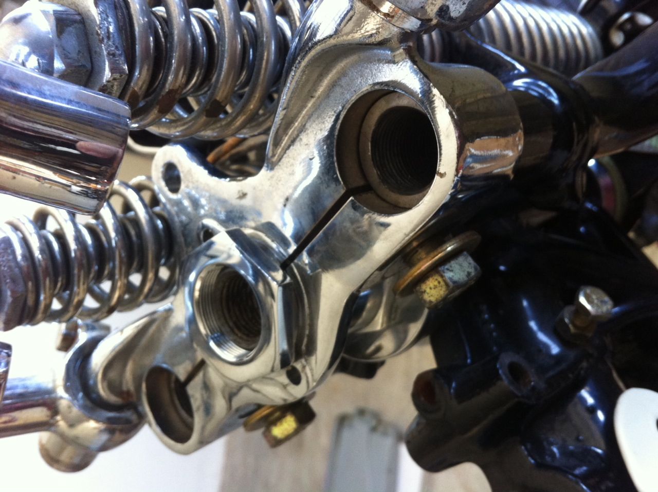
Its hard to see in there but the rear legs are threaded internal 3/4 x 16. The ID of the hole in the top tree 1" and the risers sit on top of the tree not in it. Also notice the ears with the dog bones mounted currently.
I ordered up the hex stock in 7/8 so it will fit in nicely inside the top tree.
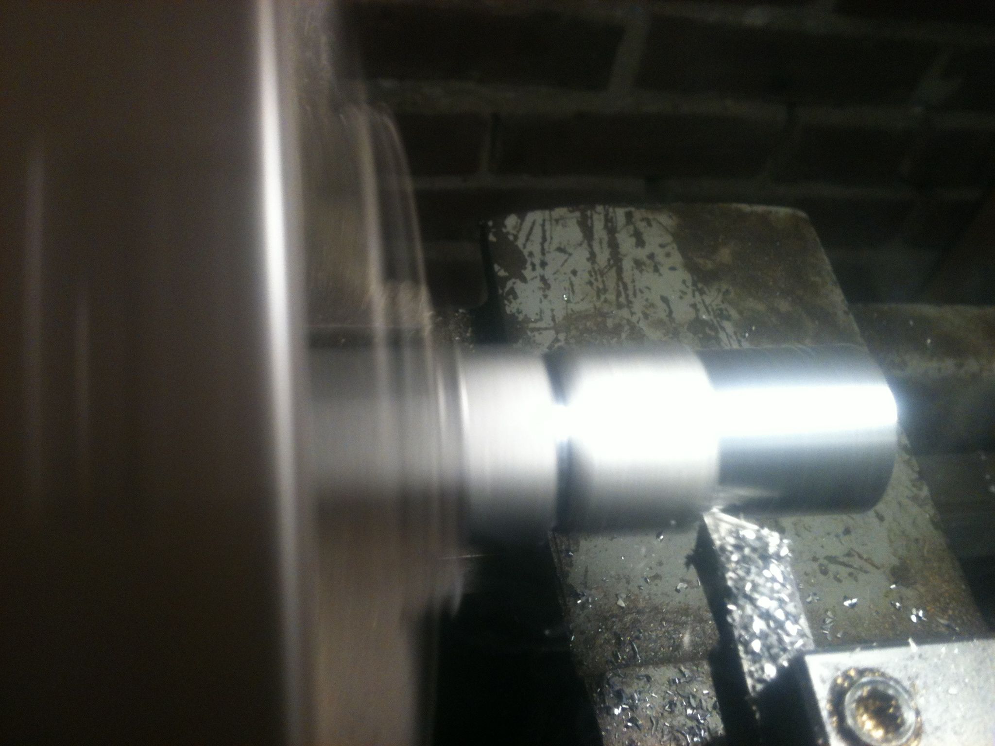
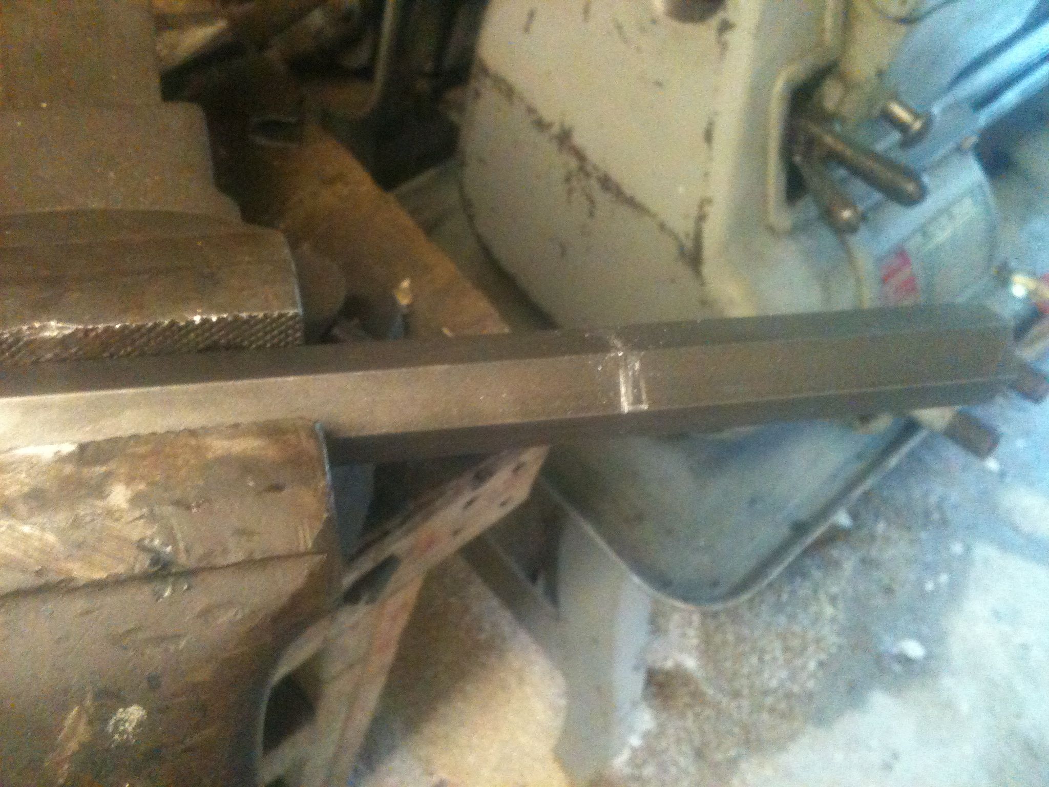
This is turning the side for the 3/4 thread to size, the half inch size has been done

RAW and almost finished.
Although Ive tried plenty of times I am never happy with the the threads when using the lathe in single point threading. Most of the time I start the threads with the lathe and get them almost to finished size, then run a die over them to finish. I did the same on these and it worked well.
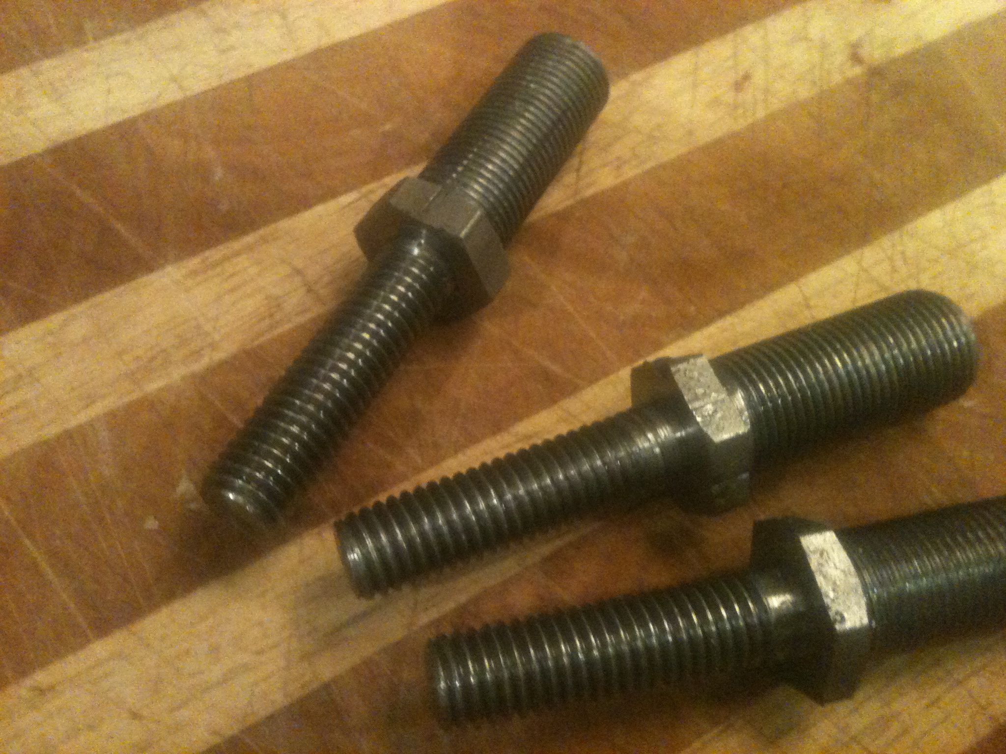
Finished product, There are three because I wasn't real happy with the 3/4 threads on one
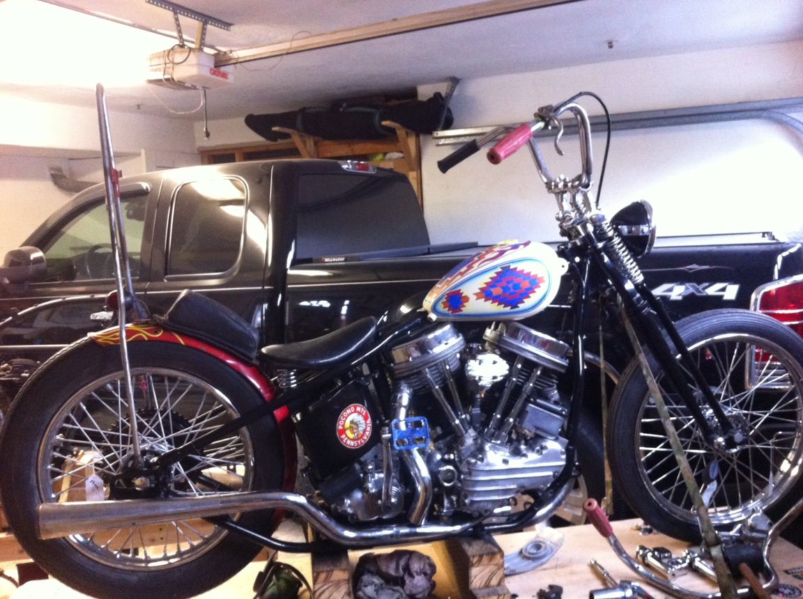
Here is the latest from Den
I bought plenty of extra stock so if any of you are looking for the same thing contact me dan@greasygringo.com And yes these are MAIDEN AMERICA
Our friend Joe Z has been putting this on for years and its known to be a good time. In memorium of MCA “Alotta Beer, Allota Girls, and Alotta Curssin”
Me, Jason and Vincent are loading up the bikes right now for a big family camping trip tomorrow. We will ride our bikes down and meet up with our families and a few from the neighborhood. Plan on a full day of riding and a Shrimp boil to end it all. YESSSS!
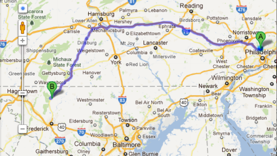
Not the route but you get the Idea

YUP
You might not see us around town much. Sure, here and there on nice summer evenings having a beer for a while. While all of us are good for a rave-up story and some beer-fueled antics from time to time, it’s really all about the metal. We like to build machines, improve them, figure out interesting problems. That’s where learning happens. That’s where interest grows and dues are paid.
On any Tuesday night, it usually looks like this. Shop in session.
Jason

Bird's eye view. I've been rebuilding the door on the '59. All internals were shot.

Dan tweaking the RD frame on the welding table

Casey getting his sporty ready for street duty
A couple weeks back I got another chance to work on this fork conversion. I just never got around to putting the pics up. Things have been hectic lately.
When we left off, we were modifying the fork to work with the original Suzuki axle for this hub. The answer to the bonus question from last round? I’d bushed one fork leg but not yet bored it to allow access to the fork damper retaining screw. Bill Becker was the first to point this out, just minutes after the article was posted. If anyone has an nit-picky eye for detail (and style), it’s him.
This time I modified the axle and related hardware to finish this job.
Here we go.
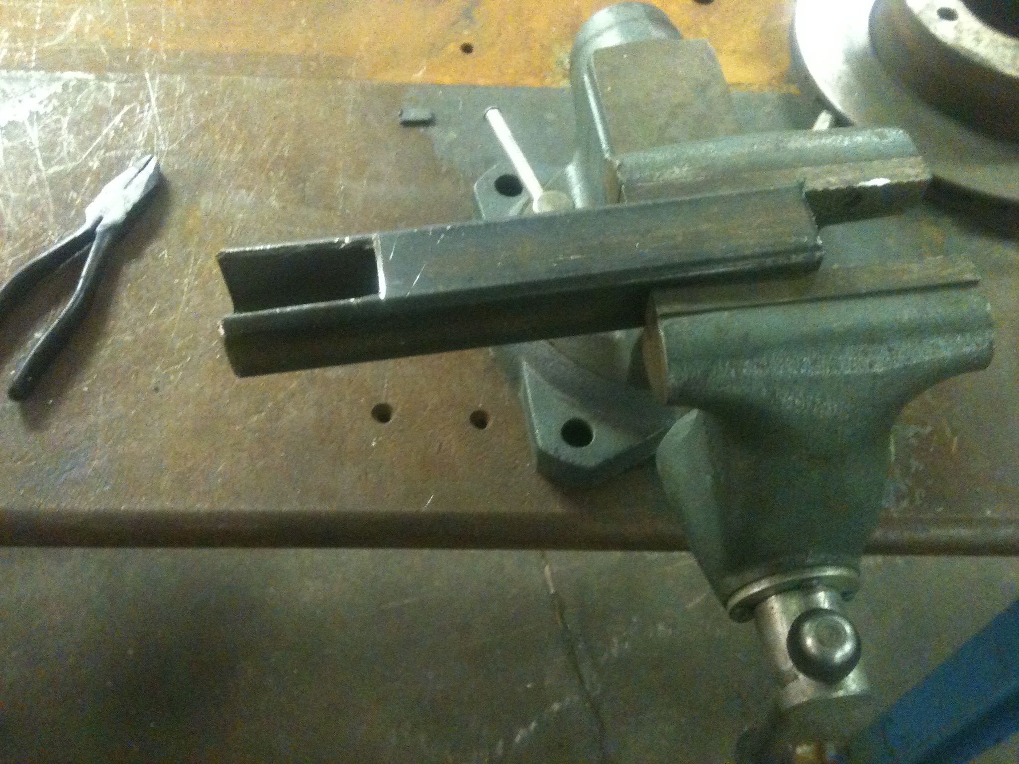
I was able to mount the fork leg to the milling machine table vertically with just enough room to get the boring head setup. However, there was no way to keep the leg secure enough with it acting as such a long lever and having limited contact where mounted. I then decided to mount an extra vice we had in the welding area to the table with a large angle plate. This allowed me to hang the leg off the side of the table so it could be clamped closer to the work area.

Big old vise mounted to an even bigger angle plate. This setup worked pretty well, even if I did scar up the fork leg a bit. Nothing a little sanding and polishing won't fix.

Leg after bushing has been bored to match existing bore in axle boss. Now you can get the damper retaining screw!
There needs to be a means to secure the axle while tightening down the axle nut. I don’t want to rely on the pinch strength of the boss on the other leg as it seems lame and likely to stress the leg. It also leads to incorrect installation as the last step of securing the wheel is to tighten the pinch (after axle nut is torqued) so that the legs are parallel and not pinched together. I decide to make a small diameter hole in the axle for insertion of a screwdriver or rod to keep it from turning. Old Harley Hydraglide forks use this setup and it works. In our case there is no axle protruding so I made the hole so that it lines up with the damper retaining screw hole under the leg. Hidden. Functional. I did realize afterward that while I intended to drill the larger end, I messed up and did the smaller end. Dammit.

Axle secured in a v-block. Located under the quill using a "wiggler" for drilling.

Axle drilled. Hole is perfectly centered. Drilling on a milling machine is so much easier.

Whole setup assembled. Note the access hole for securing the axle.

I turned down the axle nut to leave room for a lock washer and made up a thick flat washer to spread the clamping force over the original fork material and the new reducing bushing I installed. The washer has a flat ground in it to engage the lower fork casting so it doesn't rotate when tightening.
That’s it for this session. I have to drop some parts off for chrome and polish the lower legs then we can assemble this and ship it home.
Jason
With a few old pics of my own

If anyone knows what kind of Yamaha this is, I'd like to know. 80cc

First real dirt bike. I mowed about a million lawns to save the $800 for it.


Being a dad now, I don't know what mine was thinking encouraging me to jump for the pictures.
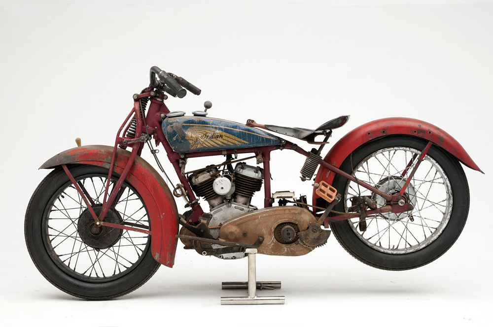
This 37 Indian Junior Scout has been up on ebay several times already. Hope someone doesn’t buy it to restore and ruin its patina.
I picked up this set of beat-up pipes for my current project. They were typical of a 30 year old part and were rife with dents and creases. Ive heard a lot of talk of guys putting water in pipes and freezing them to push dents out. I promise you this will bulge your pipe in ways you don’t want. I decided to pull the dents out using a trick I learned working at an auto body shop years ago.
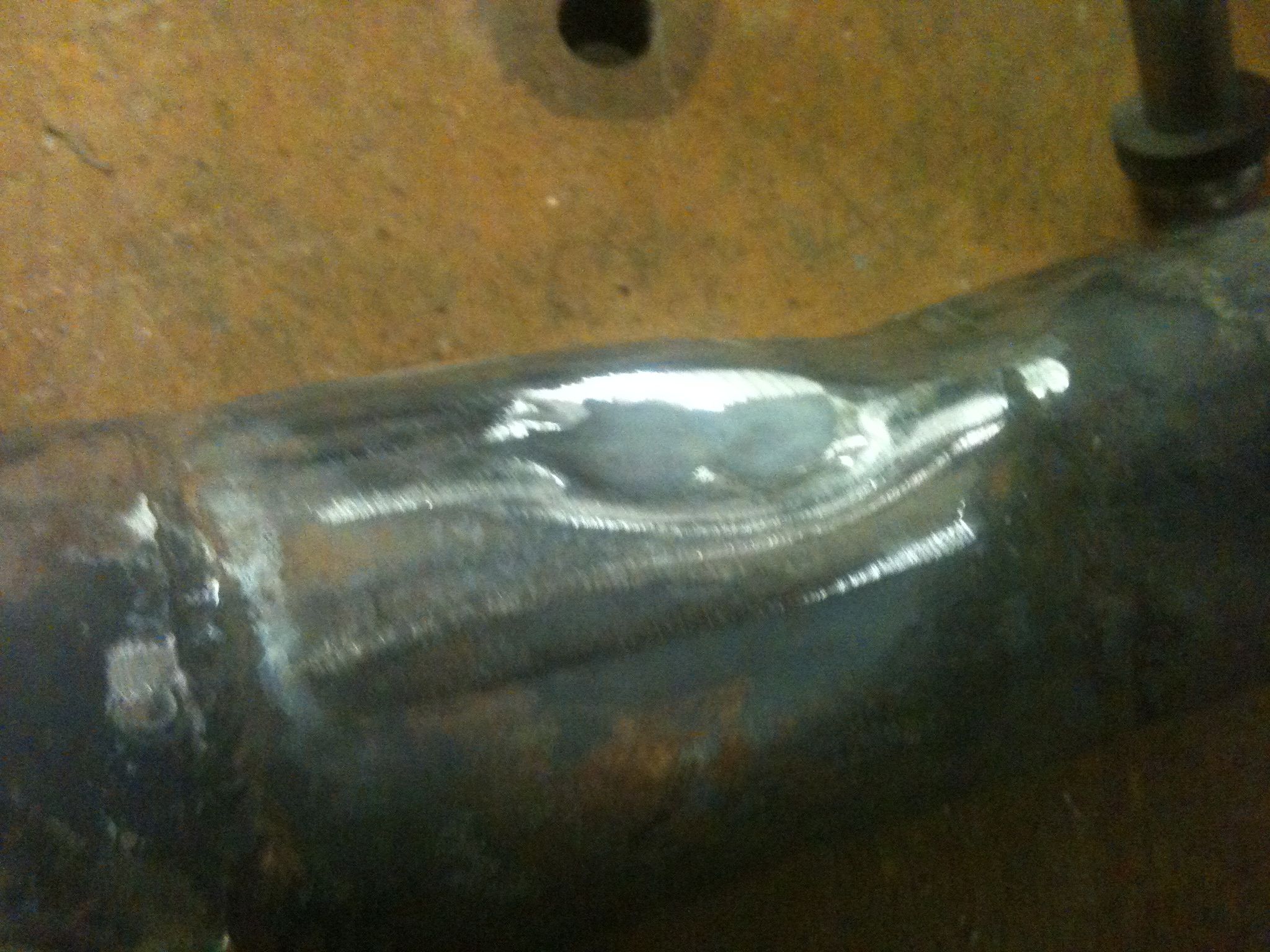
Dents
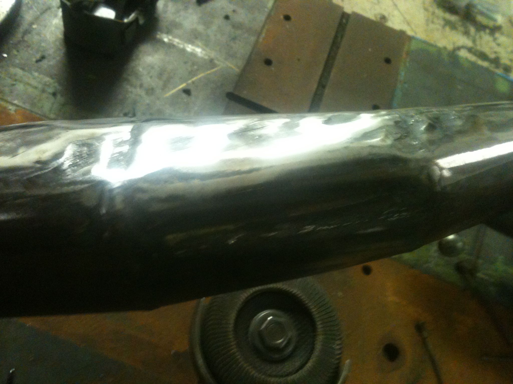
Flattened area
At the body shop we had this slick little spot welding gun that would weld studs to the sheet metal and you would pull the dents out with a slide hammer. I have neither of those, But I did have some old spokes, a torch and welder to work with.

Spokes welded to the bad areas
Heat and pull hard
pretty shapely
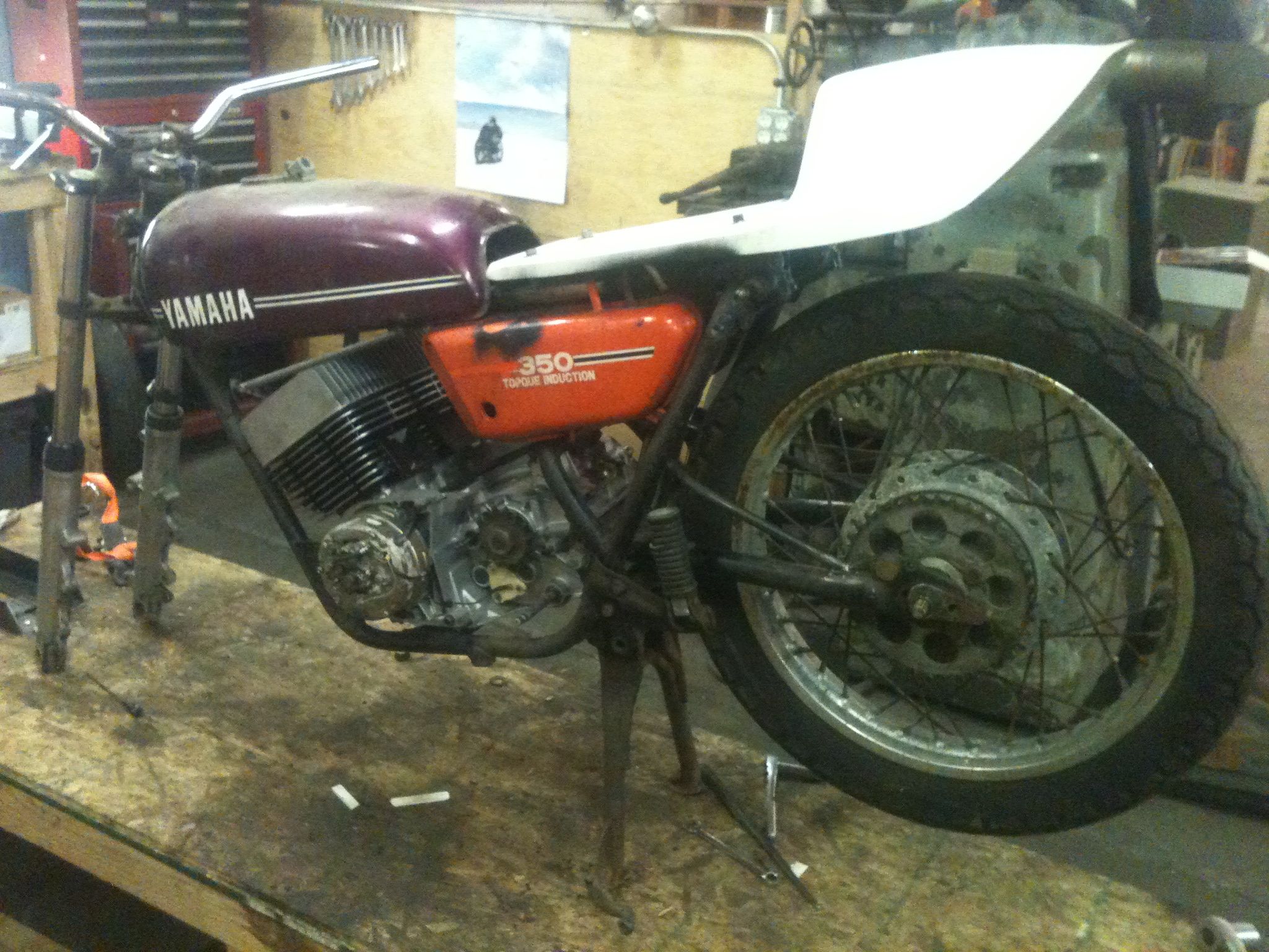
So from the beginning of building this bike I knew I wanted a bike that handled like a brand new sport bike. Rd’s wernt know for their stellar rear suspension when new and the 40 years of sitting in upstate NY made these ones good paperweights. I had looked into a few different options like Progressive and Koni and was not siked on spending the $400+ on them.
Scrap metal
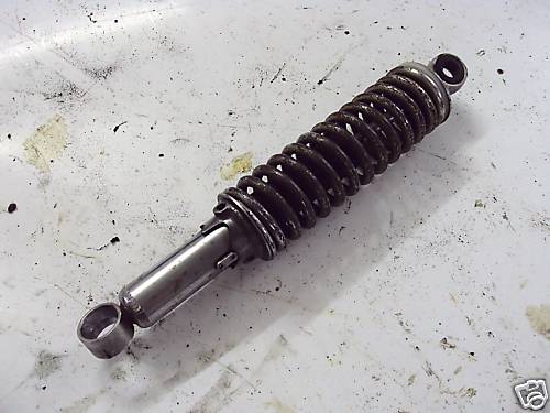
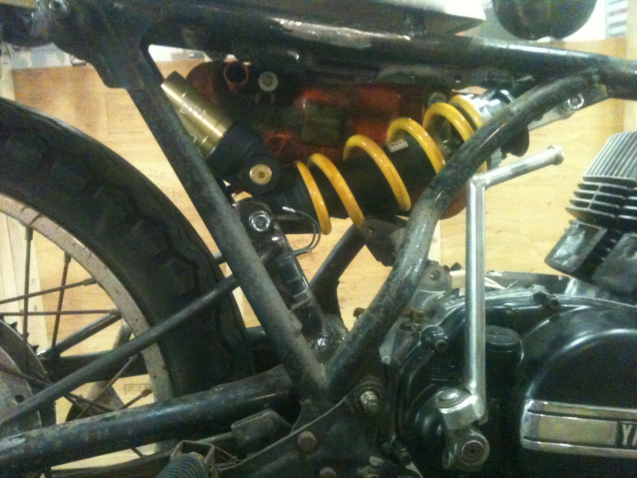
My wife had been out of town for work a few weeks and I spent lot of nights laying in bed thinking of options. What better way to get modern sport bike handling than with sport bike parts. Did a bunch of research on spring rates using the Racetech.com site and settled on a 07 Honda CBR1000rr showa unit. Its a nice unit with adjustable dampening and rebound and spring preload, plus a healthy aftermarket of parts as well. The spring rate is 11.5kg per mm and with the rd’s feather weight and my 195 lb self this puts me a bit stiffer than stock with tons of adjustments. A quick search of ebay yielded one from a low mileage bike for $25 with free shipping. I find its better to let the big bike mfg’s spend millions on R&D for their new machines and I’ll reap the benefits for my old junk.

New jawn off a 07 CBR1000rr
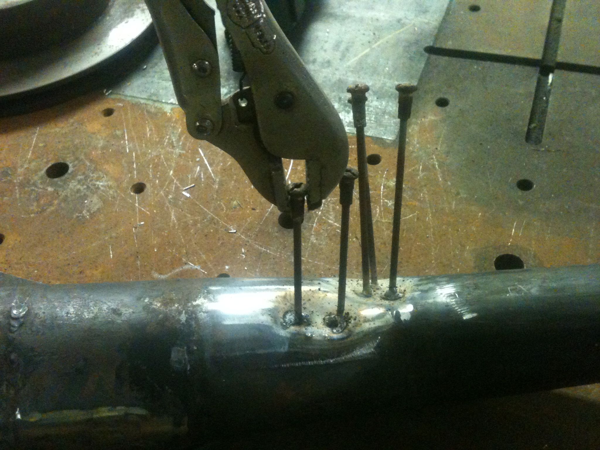
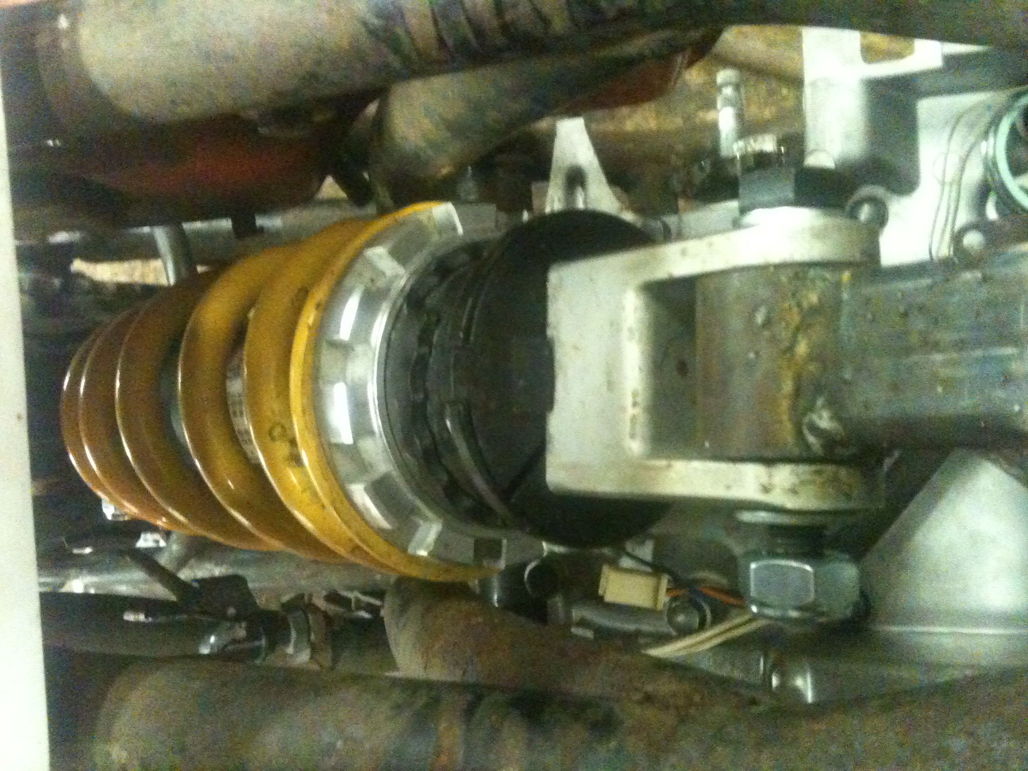
The next problem was how to make a shock with only 1.75 inches travel work in an application that needs about 5″ total with sag and not use all the fancy linkages that honda uses on there bikes. After much thought my solution was to make second arm attached to the swingarm but shorter to reduce the radius. After a lot of math I hadn’t used in years on paper I settled on needing a 5.5 inch radius from the swingarm pivot to give the proper travel when the 15″ arm moves. I decided to draw it to scale on the welding table to check the math. It worked in practice too.
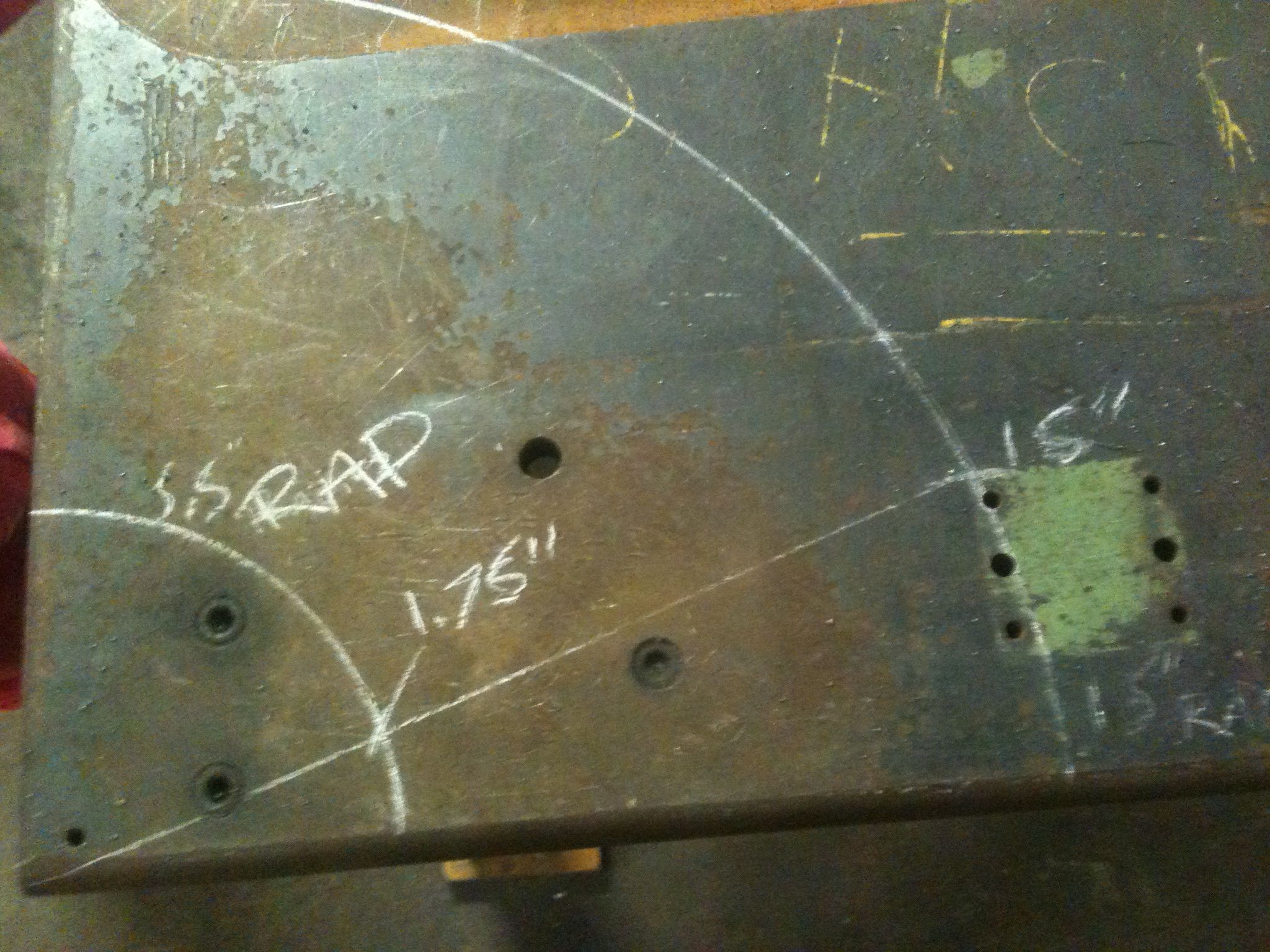
Drawn out to SCALE
Now was the easy part of tabbing up the mounts. The rear is made out of 1.5″ square stock and the front that I forgot to take pics of is a 660 bronze bush I made on the lathe pressed into some round steel stock with a shoulder on it for the shock mount to ride on.
The start of the rear mount
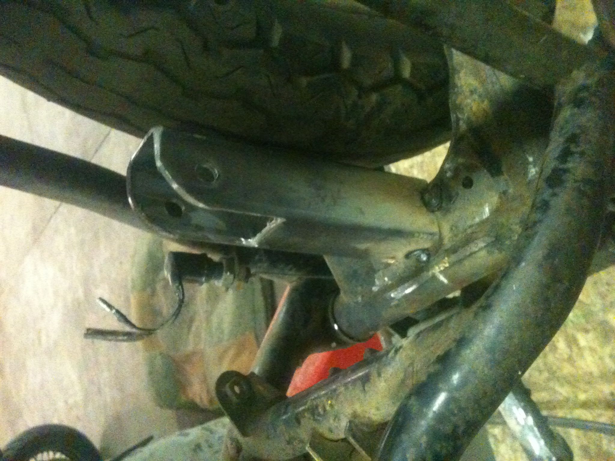
Tacked in place
I also bent some round stock to act as a gusset for the rear mount and brace the swingarm. This should help with the torsional stiffness af the old arm as well.
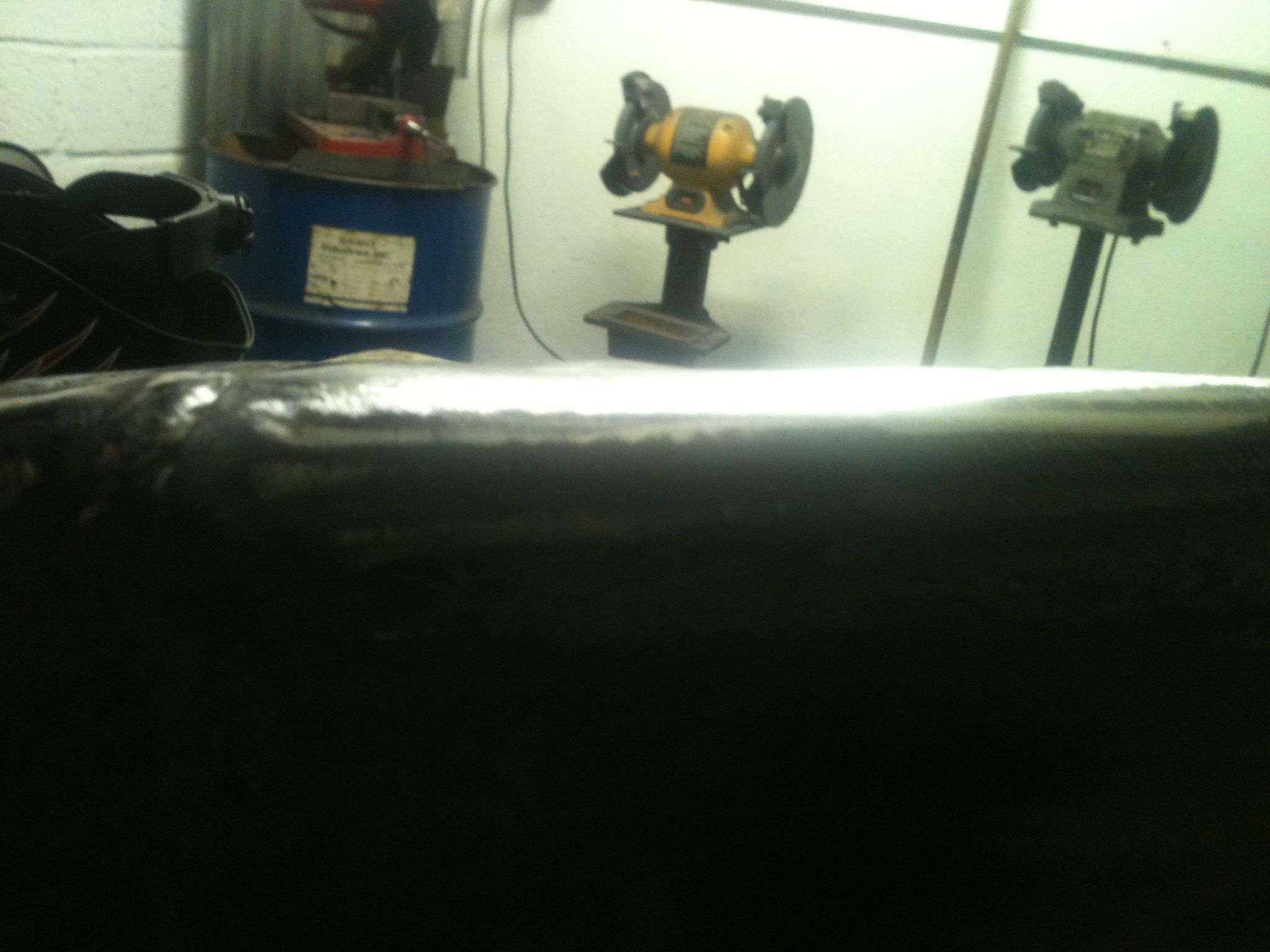
Ready for finish welding

Really cleans up the lines without the rear shocks on there