My friend JW is building a traditional British cafe racer from parts he’s been collecting for some time. He has a Norton slimline featherbed frame, a Roadholder fork, and Ariel pre-unit motor and a beautiful hand-shaped aluminum tank. He suggested that documenting the conversion of a Suzuki 4LS brake (four leading shoe) to an early Brit fork might make for a good read. I agree. Let’s do it!
This hub and brake setup is pretty sought-after for its significant stopping power and that it’s not a modern disk. I think they’re worth upwards of a grand, so I’m measuring three times for every cut. Modification is necessary because this hub is over and inch-and-a-half wider than the forks it’s going be used with.
My plan is to remove material from both the brake plate axle supports and the inside fork bosses to make it fit. The original brake stay boss needs to be removed from the fork leg and straps will have to be made to anchor the brake plates to the fender mount bosses on the fork legs. The speedo drive mechanism and associated features on the brake plate will have to be removed and welded in. A new axle will also have to be made once I get the hub fitted up nicely. I’ve decided to no attempt any lightening of this brake/hub (it’s HEAVY) as I don’t really see any opportunity for significant lightening. The internal aluminum webbing could be drilled but how much weight would a few slugs of aluminum save when compared to the four thick iron liners and various steel linkage parts? Not worth it to me. For now, JW agrees. But he’s one to tinker (and do it well) so we’ll see what he does with it after I give it back to him.
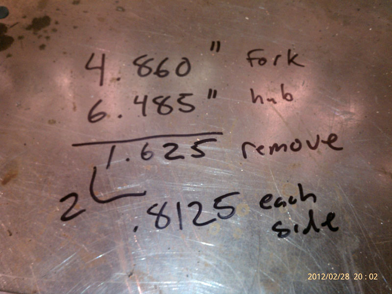
First order of business last night was to measure the fork and hub to get the final numbers for use in trimming down this hub.
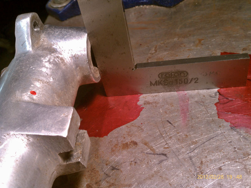
Using a square to ensure leg bosses are perpendicular to the table surface. I then scribed the table at the back of the square on each side and measured the distance between the marks.
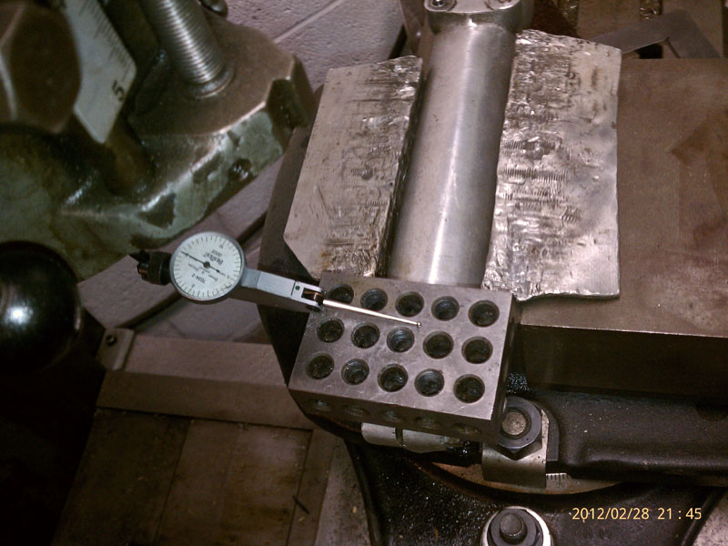
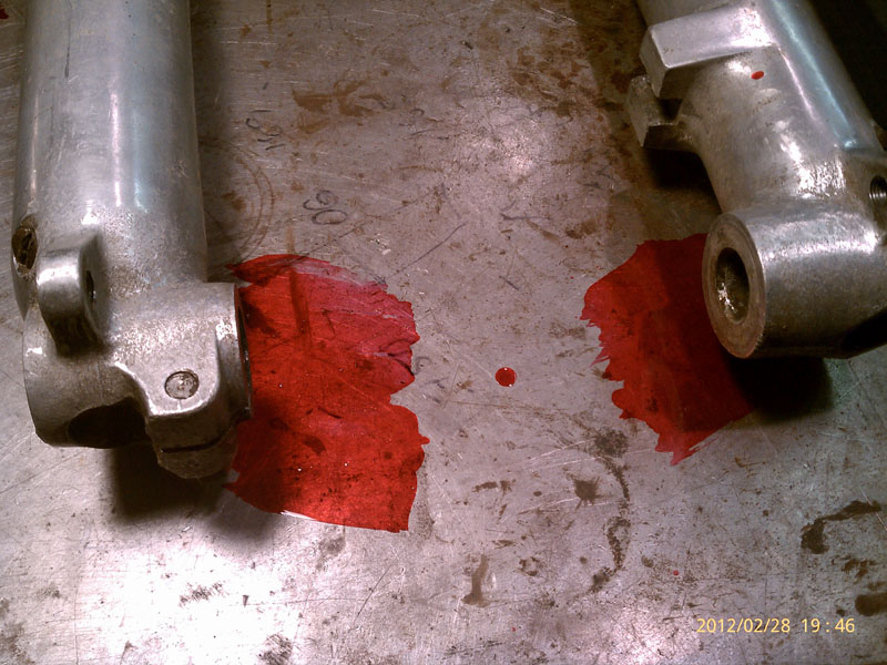
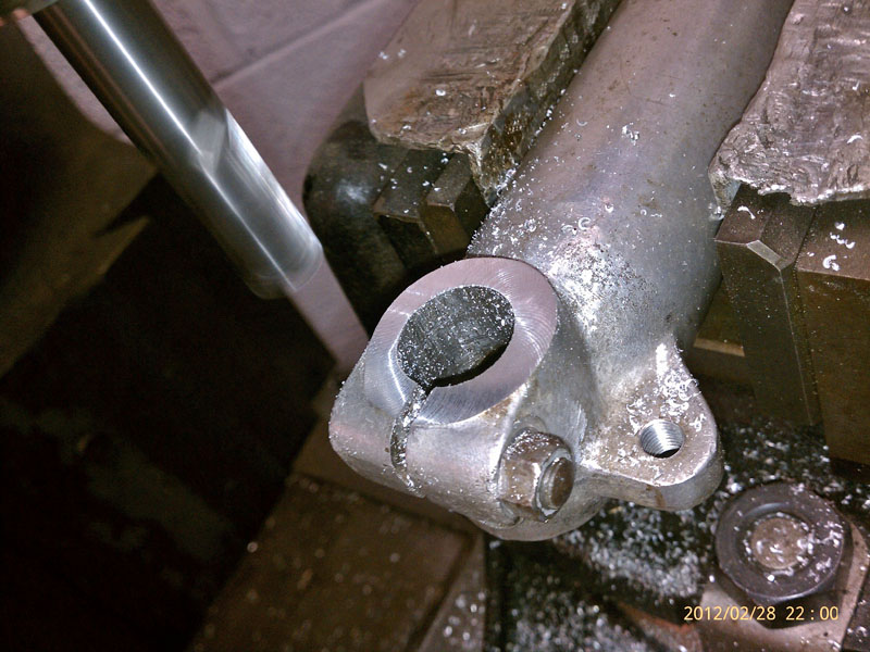
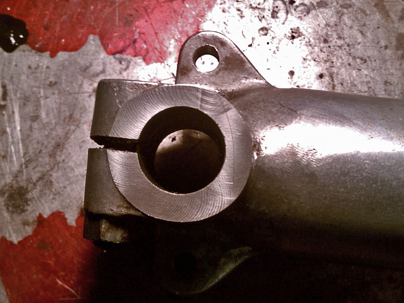
Indicating the fork leg on the Bridgeport. I can remove less material from the brake plate axle support area by taking some material off the forks.
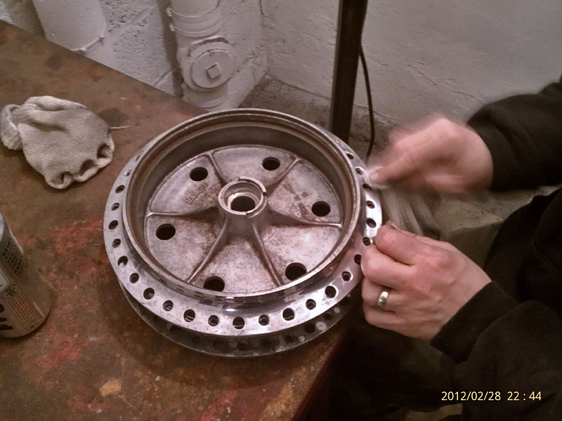
Casey generously offered to polish up all the aluminum parts. He also dressed up the brake liners. Nice work, Casey.
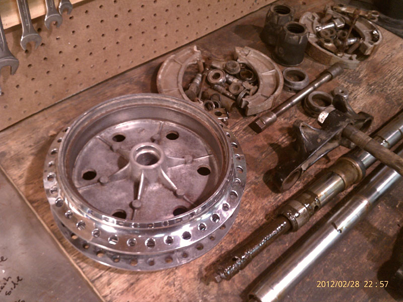
The pile. The fork internals are pretty crusty. Nothing a week-long soak in the parts washer and some wire brushing won't fix.
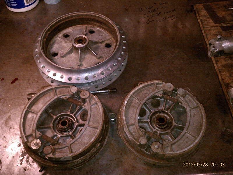
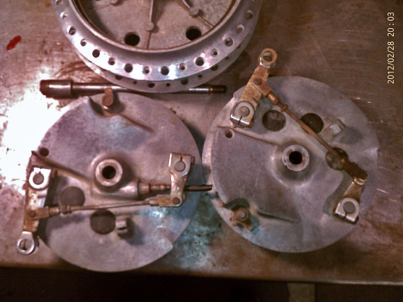
You can see the speedo drive mechanism on the left brake plate. This will have to be removed. Someone has already attempted to lighten the webbing in the hub and done a questionable job of it.
Next installment will be figuring out how to mount the brake plates the milling machine table and removal of the speedo drive parts.
Jason

Wow another nice project underway. That brake will look and work well on those forks. Keep us posted on the progress. Which engine is he going to use ? A single or twin?
Skip,
If my memory has not failed me since seeing it last summer, it’s just like this one (twin): https://www.carandclassic.co.uk/uploads/cars/ariel/2189581.jpg
you guys have way too much fun in the shop,tuesday nights are tough for me to make it up to spend some quality time…..hollar next time youse are down there on the weekend making chips and playing on the mill,love ripping shit up.
Say Hey to Casey ,Dan and VSL
Great seeing you again,gotta do it more often
40 miles each way is a long run for a couple hours on a weeknight. Especially since we’ve both got 6am jobs.
Will holler soon.
Jason
AWSOME
Thanks, Sal. Keeping busy. Not much time for profiling these days and I’ve got holes in my Vans. No cuts or patches, though. When you coming around? On the other hand I WILL get up your way this season.
use 7 3/8″th yokes, remove 1/16th” from each side off the Suzuki hub, job done, simple…………
I fitted my drum using the 7 3/8″ bottom yolk assembly from the Atlas forks and an after market 7 3/8″ alloy top yoke does the job just fine requiring minimum removal of alloy. The alloy brake reaction lump on the original Norton fork leg was turned off on the lathe (on the night shift LOL) then blended in. the speedo drive hole was ground away then it was brazed up with a lumiweld brazing rod. Then the both brake plates were machined to fit between the forks, I did not have to machine the axil bosses on the fork legs. (I have been told that there are two widths of these drums and I had the narrower drum width) I purchase a S/S 15mm Diameter axil with a sleeve to fit the road holder forks from a one off machining company on the internet. Then finally I purchased two S/S brake reaction arms also from the internet. I am very pleased with this set up. So persevere it can be done. Hope this helps