
Last weekend I had the pleasure of spending the day at Jason’s shop with his son and Angry Dan. We took to task the final setup of the head for my LSR Bike, the seats needed to be cut, especially the exhaust to allow more clearance to the piston. I had previously cleaned up the casting flash in the intake and exhaust ports, smoothed out the short side radius, enshrouded the valves and polished the chambers. Any little bit helps right?
Big E in his truck
First step was to see where the contact band was between valve face and seat. This was determined with a little layout fluid and the lightest lap. Initial findings had the contact area way out on the edge of the seat, This was good as it would allow the seats to be cut to sink the valves in a little further for that much needed clearance.
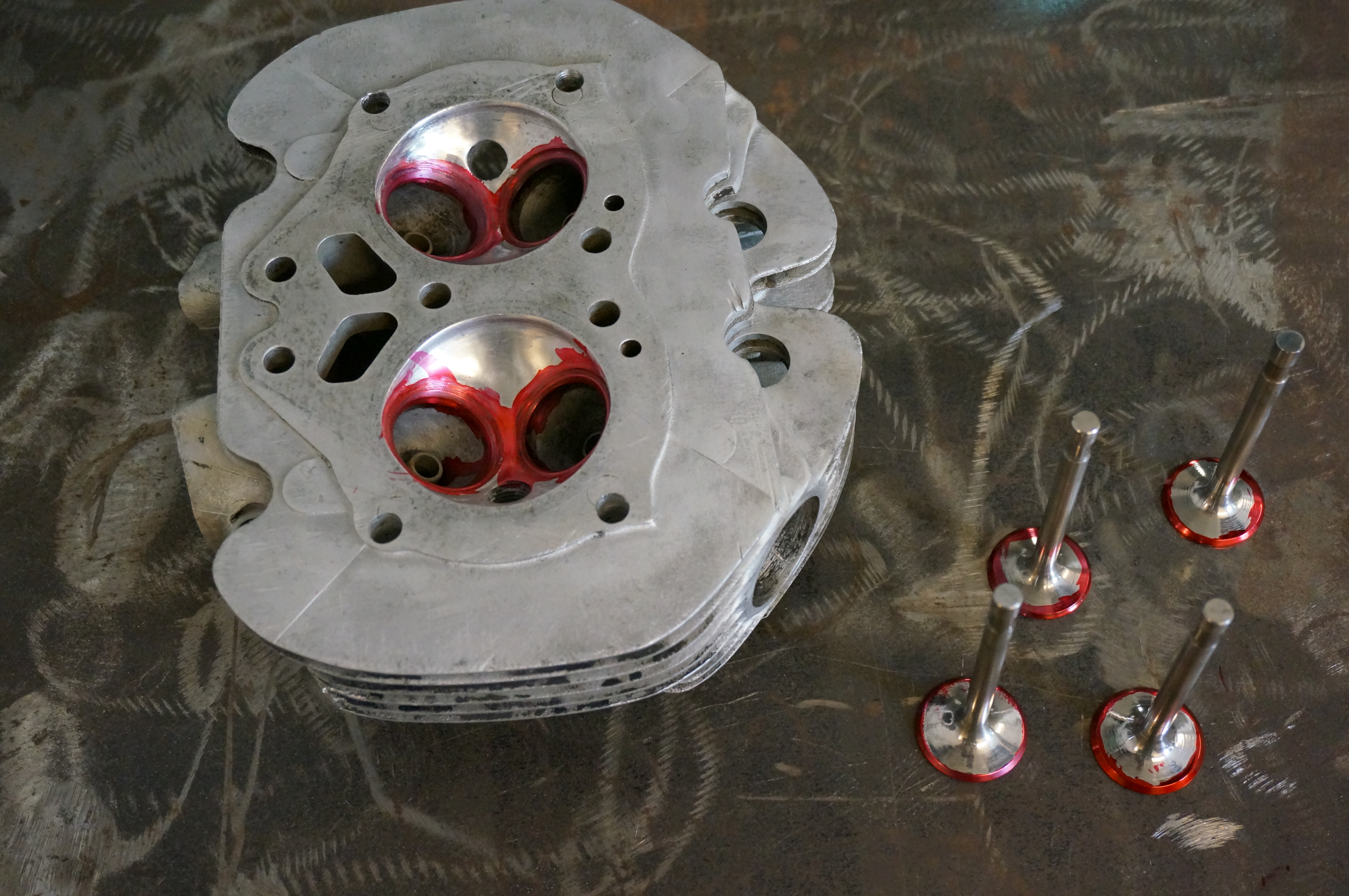
The baseline test
We used Neway cutters to cut the seats. Its a neat tool, there is an adjustable pilot that fits in the valve guide to center the cutter on the seat. There are 3 angles to smooth the flow into the port. the center angle is 46 degrees to coincide with the 45 degrees on the valve . This gives a very narrow band to make the seal and not transfer too much heat to the valve
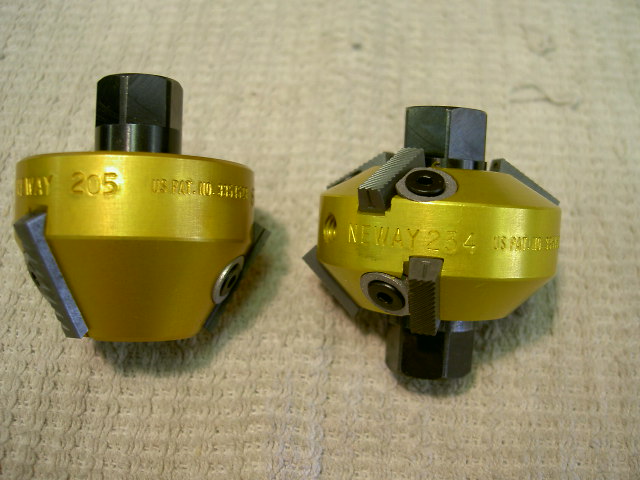
Valve seat cutters, notice there are 3 angles
After all the seats were cut with both cutters and a check was made with a bright light for sealing it was time for the final test. I used mineral sprits with some ATF in it for dye. Real simple, invert head, put in fluid, look for leaks in the ports, Both turned out well.
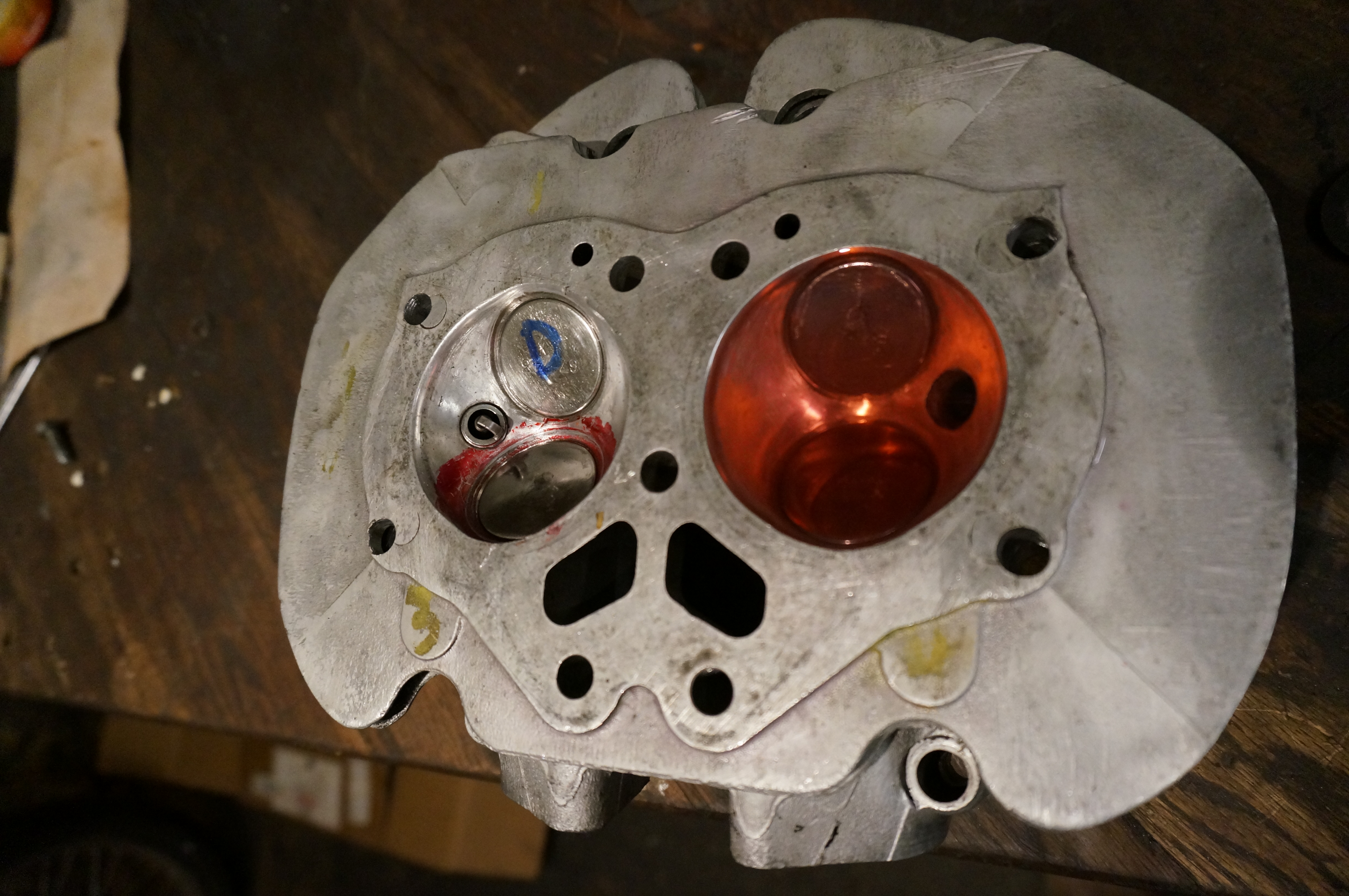
Holding strong
With that all done it was time to move on to the springs. In a previous post I had mentioned the spring setup I am using, Its a mix of BSA, Ford, and Triumph parts and some Titanium retainers. These are single springs unlike the traditional inner and outer found on most engines
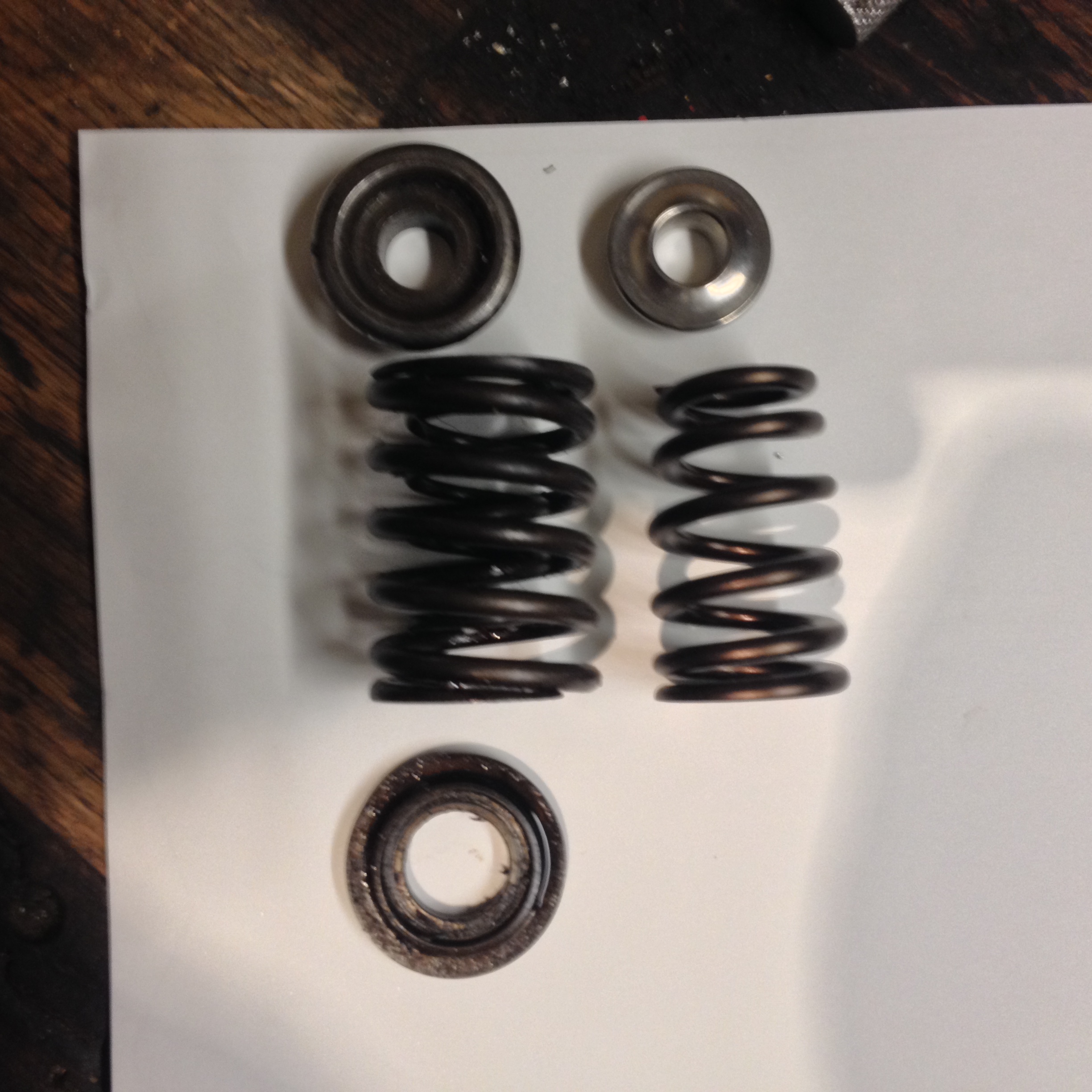
New spring on the right
Before fitment I had to turn down the bottom retainers to accept the new springs
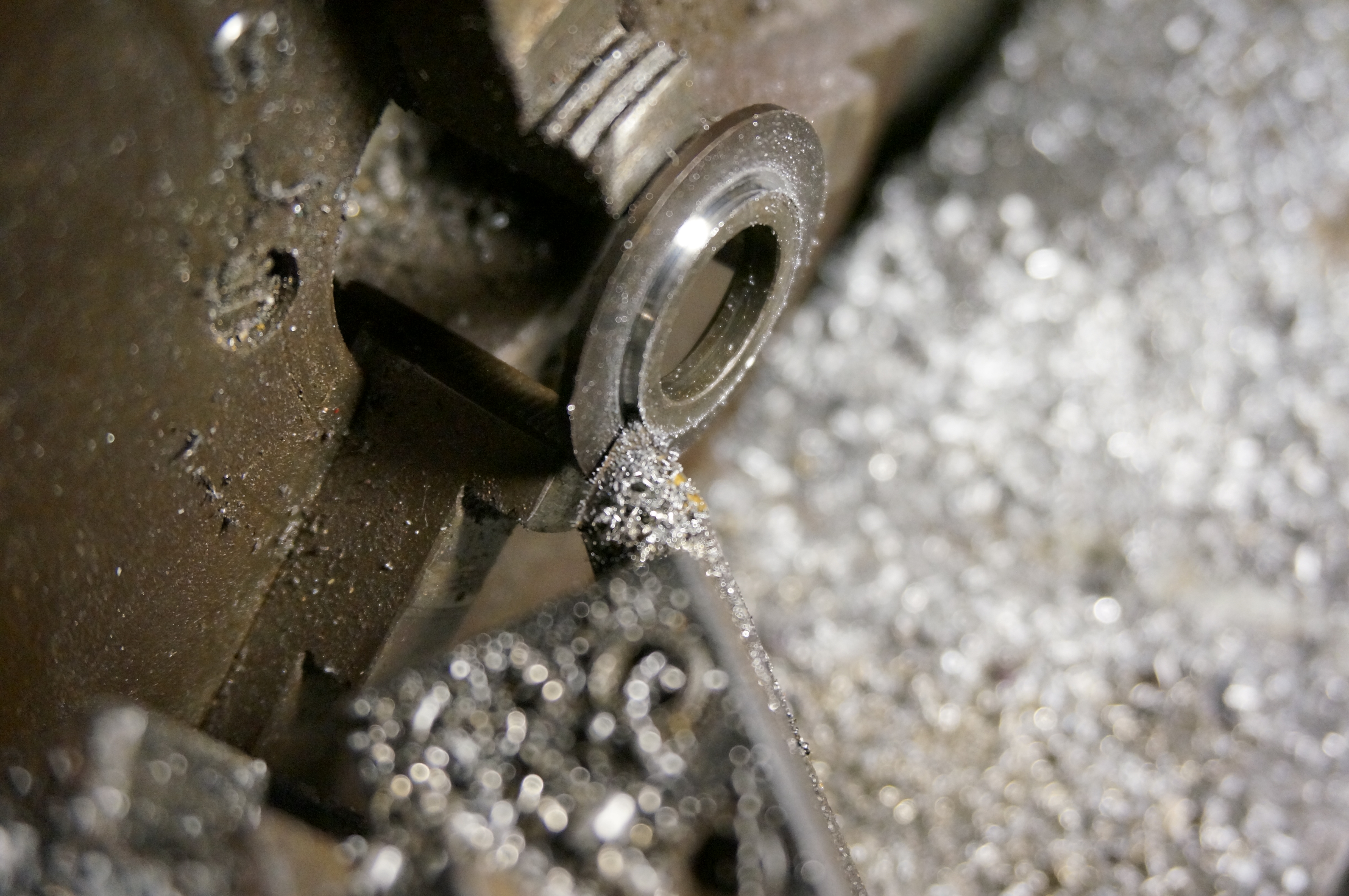
Turning the retainer to fit the ID of the spring
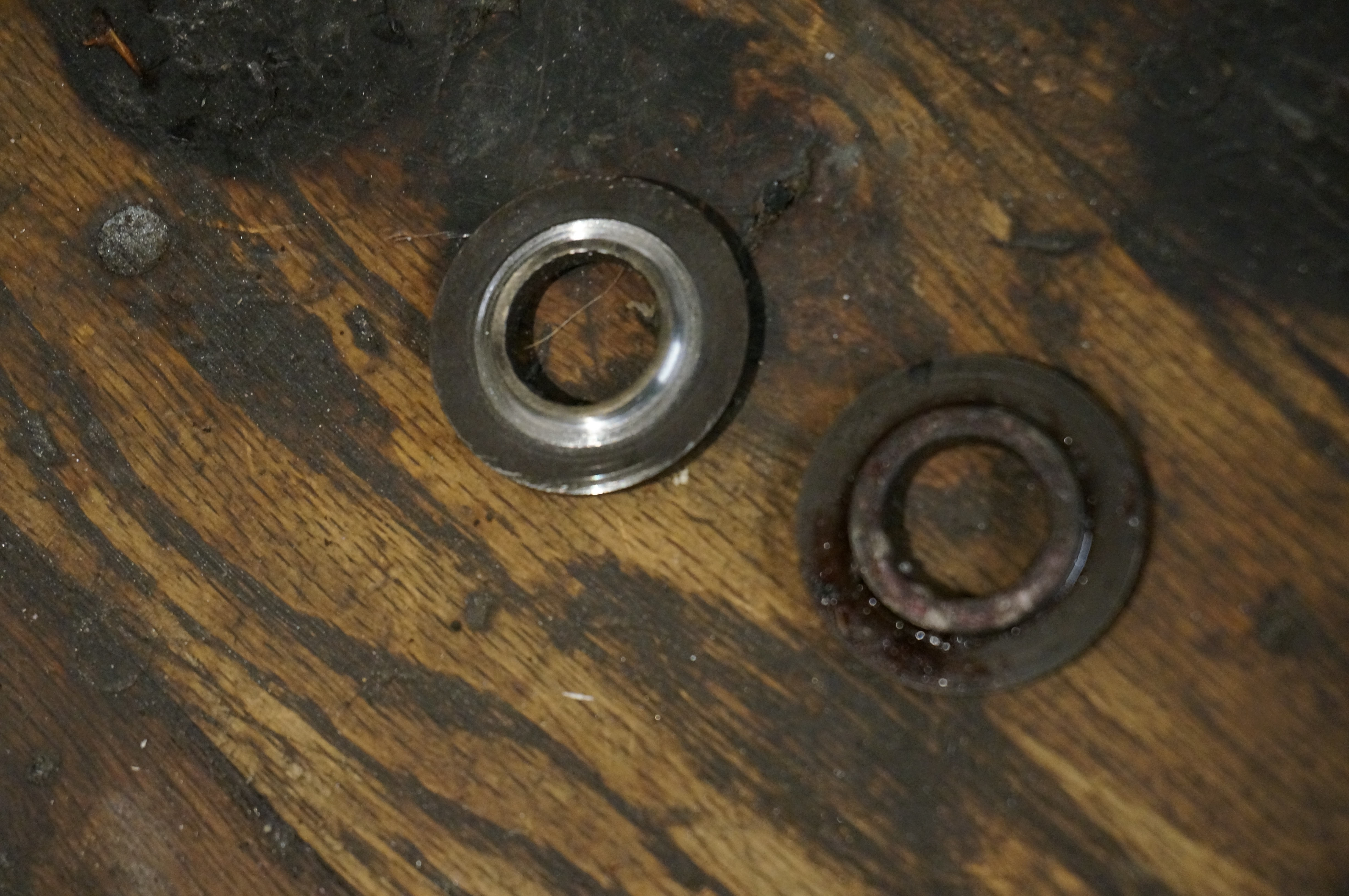
Ready for install on the left
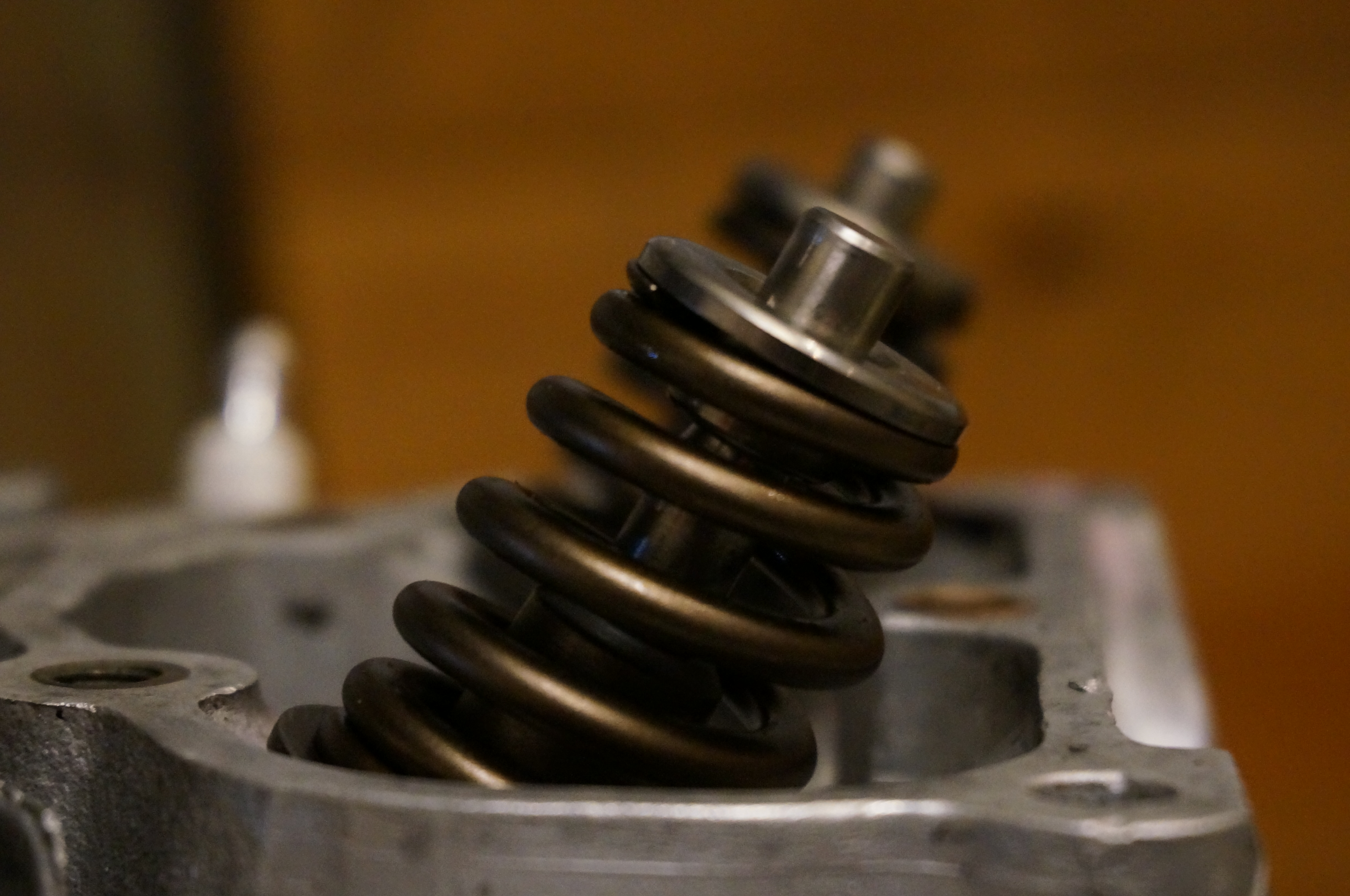
Once the bottom retainers were all turned down to accept their springs it was time to set the Valve seat pressure. I installed all spring with the components I was going to use on EACH one. Then measured the Installed height of the spring from a referencable spot on the assembly. I then took this measurement to the arbor press and with an anvil mounted scale compressed the spring to the seat pressure I wanted and measured that from the same reference. This allowed me to get the difference in height needed to hit the target number on pressure.
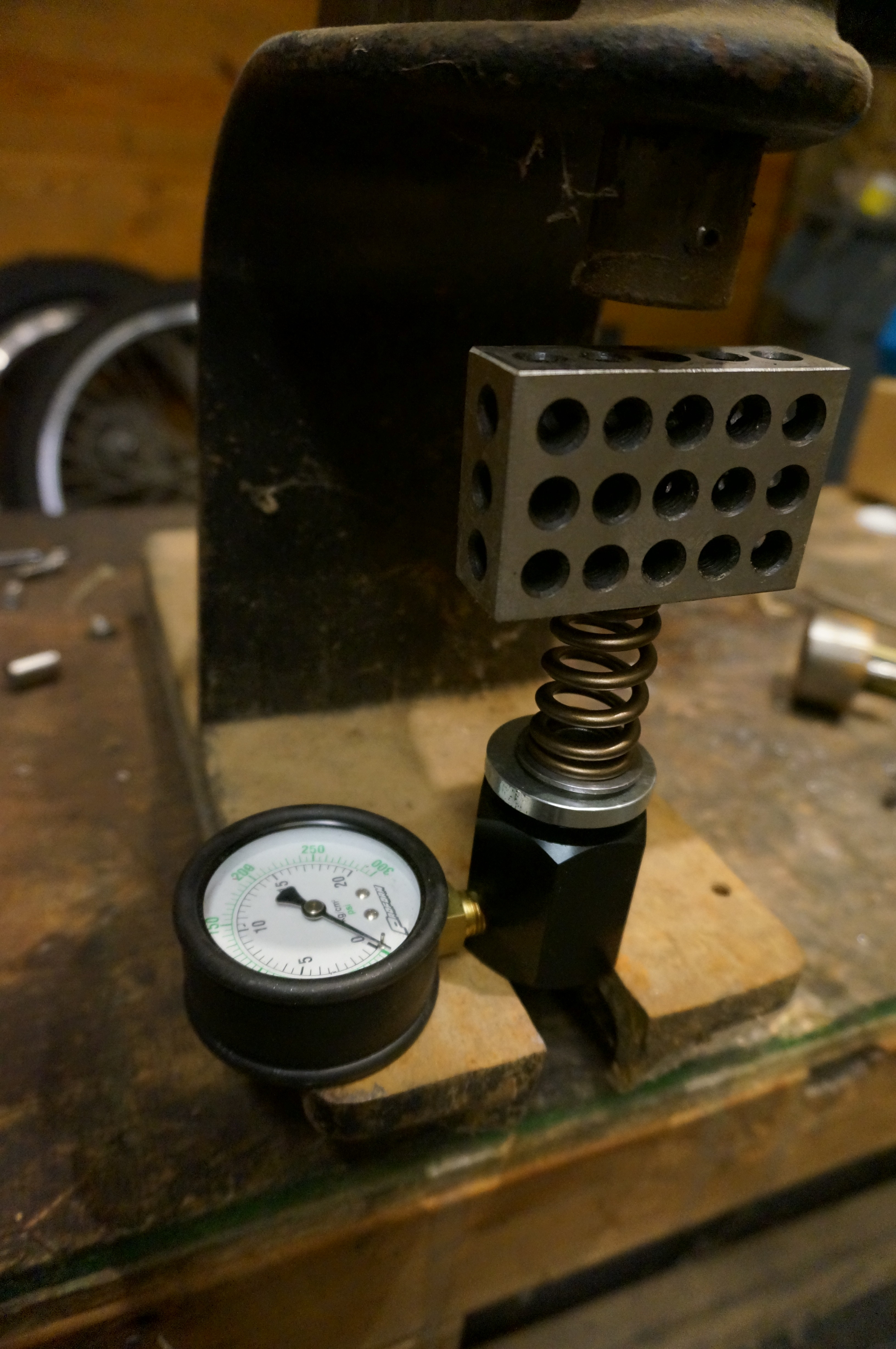
Mounted and ready for pressure measurement
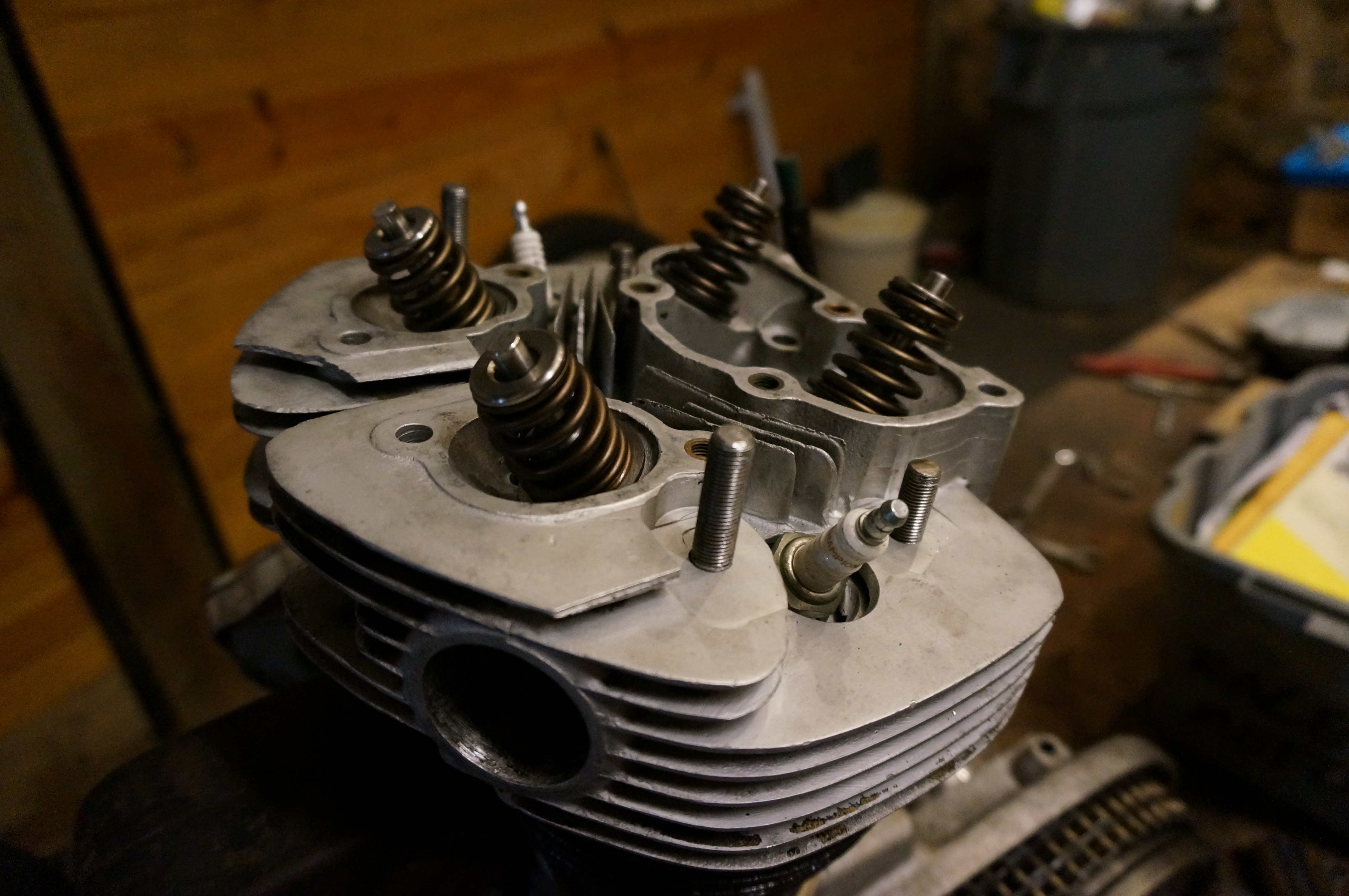
All four valves required various amounts of shimming to get to the magic number. Here is some shots of the final setup installed on the head
-Cheers DAN