Truing The RD Crank

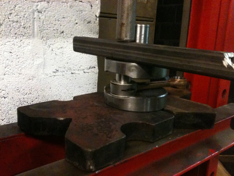
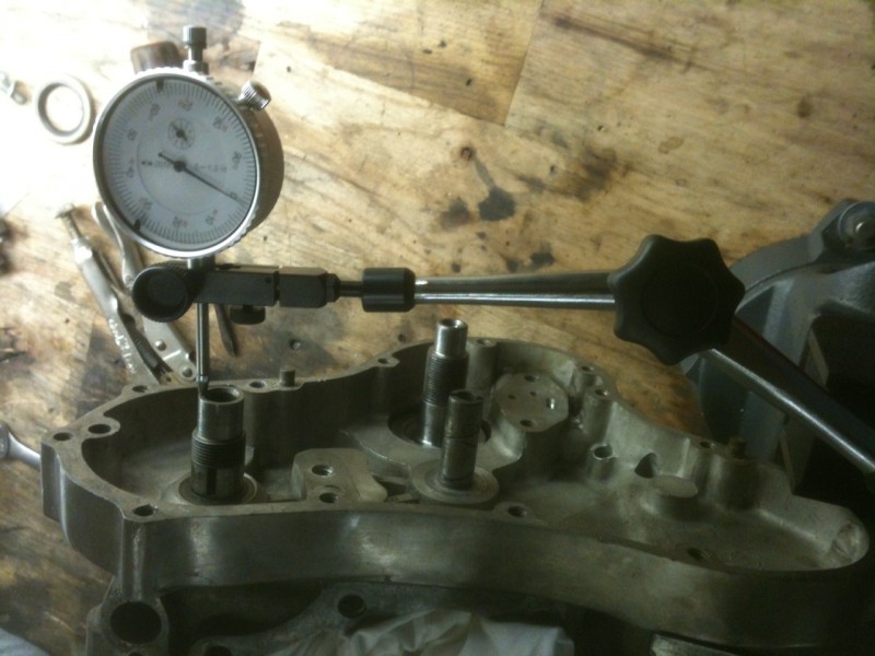
By now Im sure all of you are banshee and Rd built up crank experts. This week we will be truing the crank. With the assembly being built up of 6 parts there are plenty of places for it to be out. The spec we will be shooting for is .02mm or .000787 in, thats seven hundred eighty seven ten thousandths. There are three places to check this “trueness”, on the two ends of the crank and in the center bearings. If you paid someone to do this this is where money all went. We will support the crank on the center bearings and take our measurements with a .0005 dial indicator mounted on a magnetic base.
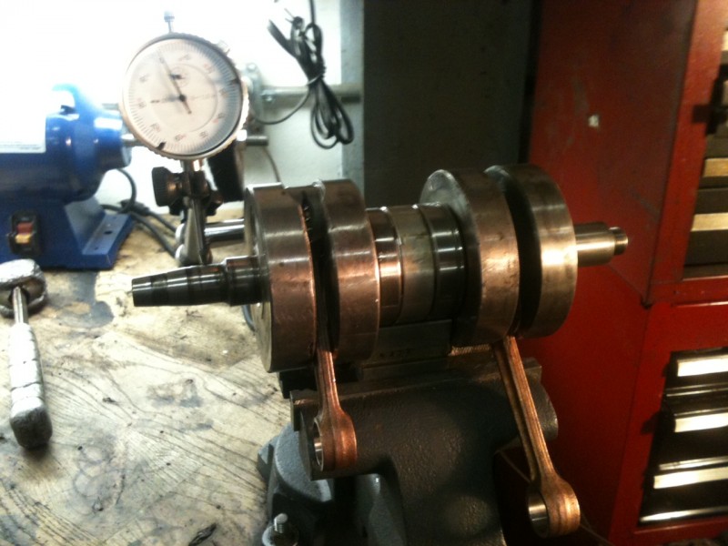
First we set the crank on the V block and spin it through supporting the rods and making sure there are no hang ups. After you establish that you spinning free its time to put the indicator on it and establish a baseline as to where its out . As you can see from the drawing below there are 4 planes we are checking in. We’ll call the crankpin 0 then 90 degrees going around the crank, 180, and 270 respectively. 
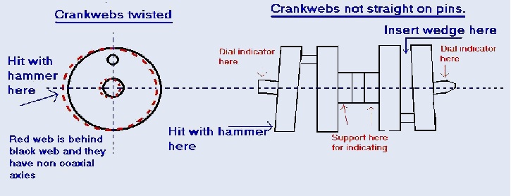
Rotate the crank checking all these and see the chart as to where you should hit to correct it. Don’t be shy at first, my crank was over .040 out when I started and it took a good while to get my arm calibrated on how hard to hit it. Check all points after each time you adjust he alignment. As you get close you will want ease up and just lightly tap it to bring it home. It took me about 45 min to get it within .001 and an additional 30 min to get it to .0005 where I left it. Well within spec and at this point Don’t breathe around it as you might just throw it off a few 10 thousandths.
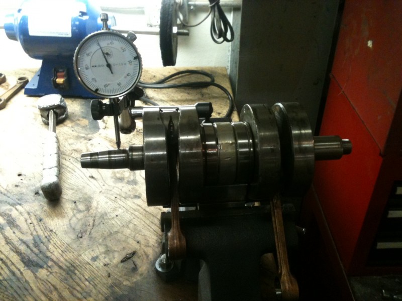
 -DAN

Rd350 built up crank assembly

A few of you may of seen the pair of RD350’s I picked up a few weeks ago and there subsequent tear down. This will document the rebuild of the crankshaft. As I type the cases are out in Oregon being vapor blasted HERE, a process similar to glass beading except that its done with a slurry and produces a superior finish that doesn’t stain as easily and looks like the day the part was cast. In the meantime I have been sussing out different things on the bike and gearbox, removing unesscary tabs on the frame and collecting parts for the rebuild.

Having dissembled the the crank to inspect,I found out I would need new connecting rods and bearings in addition to the 4 main bearings that support the crank.

CRANKPINS, the big ends of the rods were just as trashed as well as some bluing form heat


While I neglected to take photos of pressing the crank apart it is almost the same as reassembly.

All apart with the pieces that will make it new again, also note the slotted con rod for better oiling

objectives are: Make special fixture to support the crank while pressing it apart and not bend the rods.

Almost fold the press and or explode my push bar to sepiarate the center webs that have been married for 40 years.

Catch crank halves as they fire out the bottom of the press.

All this has been accomplished by the simple fixture I made out of some large square tube with a half a dozen rags stuffed in the end and a plate with an notch cut out for the crank pin to sit.Crank pin in, rod and bearings and thrust washers on

The most difficult part of reassembly is pressing the two sub-assembles together while maintaining the rod side clearance at .001-.003 You can’t see from the pictures how I accomplished this with two pieces of bar between the crank webs. This proved difficult as the clearance I wanted to maintain went away to almost nothing, at least it prevented me from bending the crank pins! Because of this I had to reset the side clearances, not  big deal but a little harder than while it was still the sub-assemblys.  This is the point where I began to get frustrated and stopped with the photography class. After a bit more futzing around I was left with an assembled crank. Next installment will be truing the crank, STAY TUNED!

Chris’s Norton mill goes together

Sunday night I met Chris aka Goodwill down at the shop to put his Norton Commando motor together. While he has never built a motor before he has a pretty good mechanical knowledge and I get the pleasure of working with him 5 days a week to answer all his questions. He’s been coming down to the shop on Sundays and tuesdays for a few months quietly working away. Ive been pretty busy with my other projects so I haven’t been paying much attention to what he’s been doing. All his busy work of cleaning bolts, fixing threads, and sorting what goes where paid off on sunday.

He will be running one of those fancy superblend bearings on the drive side an a ball on the timing side to control the crank end float.

Chris heating up the cases to accept the bearing race

Crank has been built up and the rods polished by Classic Cycles in frenchtown NJ, you could comb you beard in the reflection of these things. We put the bearing in the “bearing shrinker” aka shop fridge for a while and sorted a few things out. After sufficient shrinking time Chris fired up the heat gun and heated the cases to install the bearing. It dropped in for install with no hamfistery needed.After that, we used sufficient force to assemble the case halves for a dry run on the end float of the crank and camshaft. 2 or 3 tries later we had the float within acceptable limits on both and were ready to jizz them together.We fitted the halves back together one last time and torqued the bolts to: just tight enough in/lbs, checked it one more time and had a Beer. PERFECT SUNDAY