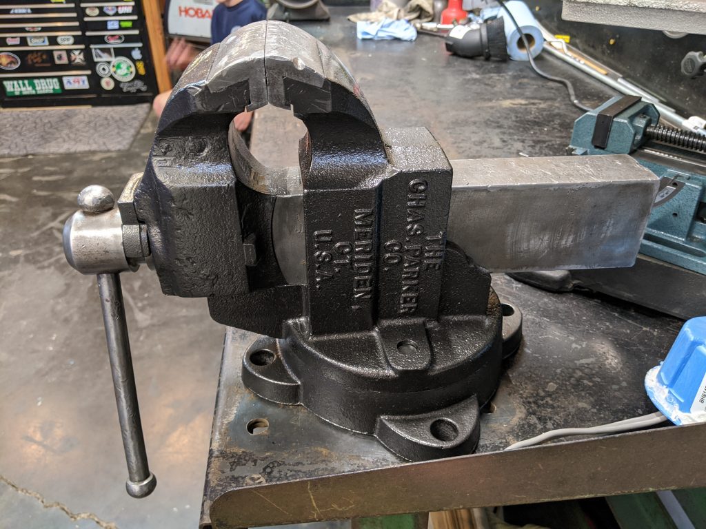
Rebuilding an 80 year old Parker 974 vise

I’ve been fighting COVID-19 lock down boredom by keeping busy with a constant diet of projecs in my garage and around the house. It’s been six years since I created an article here, but boredom is the enemy so here goes . . .

A lot has changed since my last transmission:

  • I moved away from Philadelphia with my family to take a job in California.
  • I moth-balled my workshop (the one you see in all previous articles here) and took what could be shipped with me when I moved. The heavy machinery still lives in Philadelphia.
  • As my sons grow and learn (they are 6 and 9 currently) I try to teach them the project mindset with everything we do. Guess this is NOT a change since last time ;-0
  • All projects are now down in my small-by-comparison two car garage. I’ve gotten back to basics and am enjoying it. I’m also employing some of my old methods of getting things done without all the fancy machining tools although I do still have a lathe.

The house I was renting when we first moved here had an old garage with a hand-built workbench and a nice old vise. I used it for three years and became attached to using it. I asked the landlord if they’d sell it when we moved (after buying a house two doors away) but they told me it was their grandfather’s and had sentimental value. I can certainly appreciate that. So I have been looking out for listings off and on for the last few years for a Parker 974 just like that one.

Two weeks ago I found one at a decent price with reasonable shipping charges, free in this case. Weighing around 80lbs, shipping cost is a big consideration. This one comes from Connecticut and has definitely seen some hard use but nothing is broken. My intent is to actually use it (more hard use!) so this suits me fine.

When it got here I was impressed by the care the shipper took in crating it. That’s always a good sign. I was going to just bolt it down and use it but then spontaneously disassembled it and starting cleaning it up and looking for any needed repairs. The rest of this article tells the tale.

Nice to be back.

Jason (May 2020)

(click on pics to see full size)
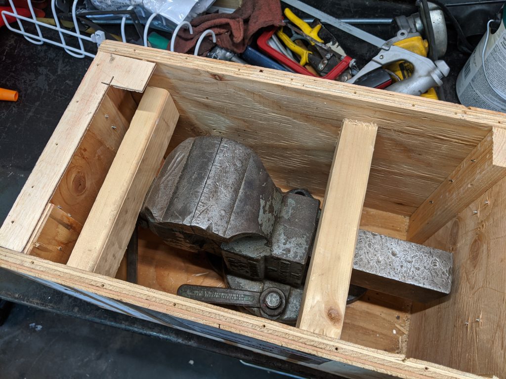
click on image for full-size view
This is how the vise arrived. Well made crate with the vise secured inside. I half expected it to arrive packed loosely in a huge wood box . . . and bent or broken.
click on image for full size view
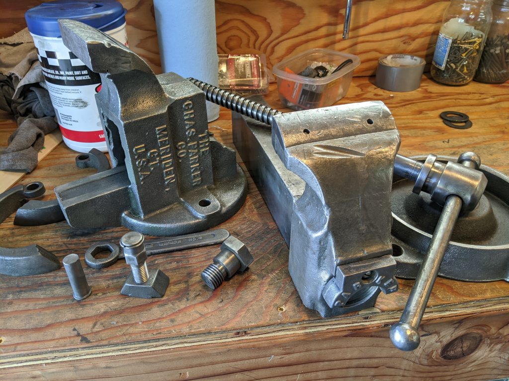
Within an hour of having received it, I had it complete disassembled. I used a wire wheel to strip three layers of paint away. Was originally black, then someone painted it mint green, then someone painted it machine grey.
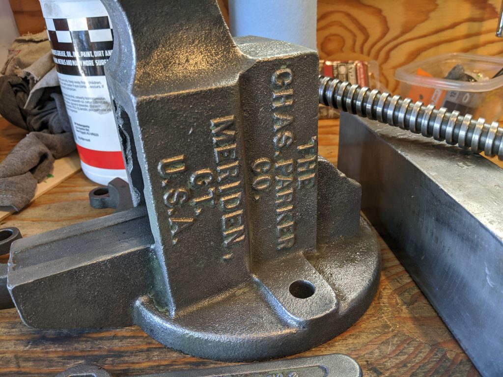
Main vise body/receiver after stripping and inspection. No cracks. All good. This is a stout casting.
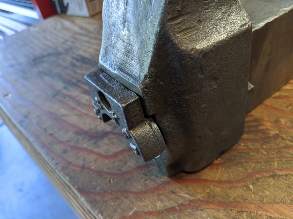
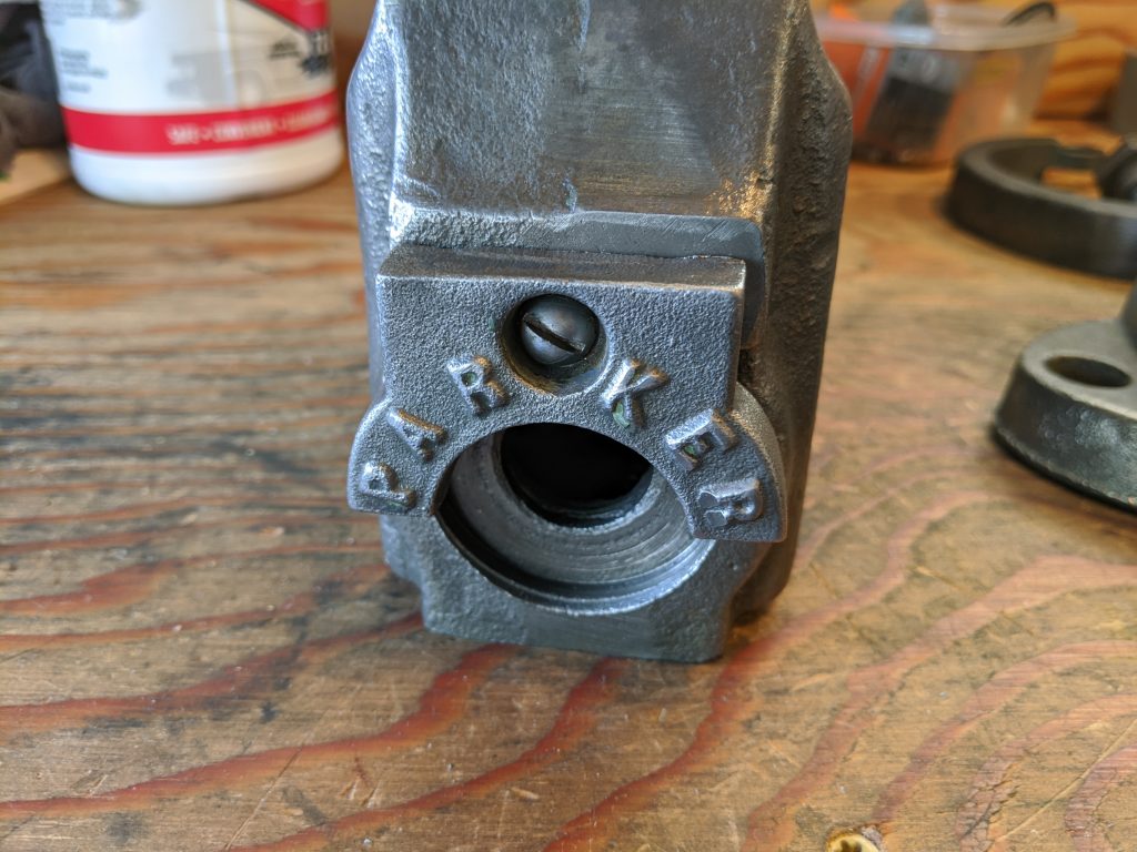
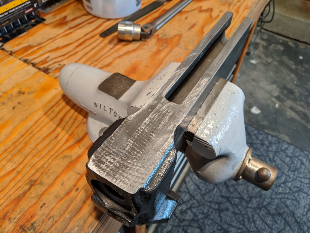
The slide jaw retainer (connects the main screw to the sliding jaw for opening the vise) had a large gap where it meets the jaw. Didn’t matter for 80 years but I ground it down for a better fit anyway. I’ve got the time.
Sliding jaw retainer after stripping and repair for better fit.

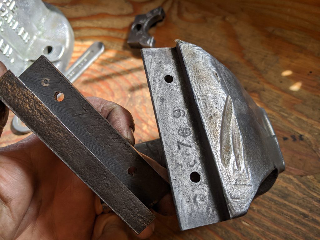
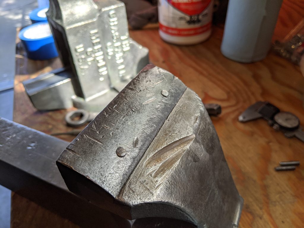
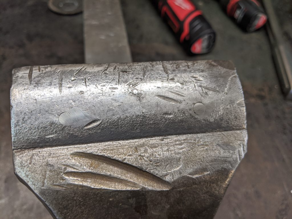
The hardened steel replaceable jaw was loose when I got it. They are pretty tough to find once broken so I decided to fix it. The holes are for press-fit steel pins used to secure the jaw to the casting. I removed them with a drift pin and took a pic of the part numbers for future reference.
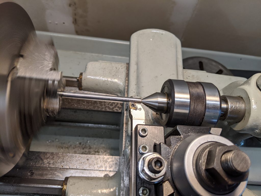
Making new slightly oversize pins to secure the jaws. The ones I removed were around .008″. I did not inspect the holes so I just made the new ones at .010″ to force them in place for a secure fit. Lathe is a 1944 South Bend 10L I recently put back into service.
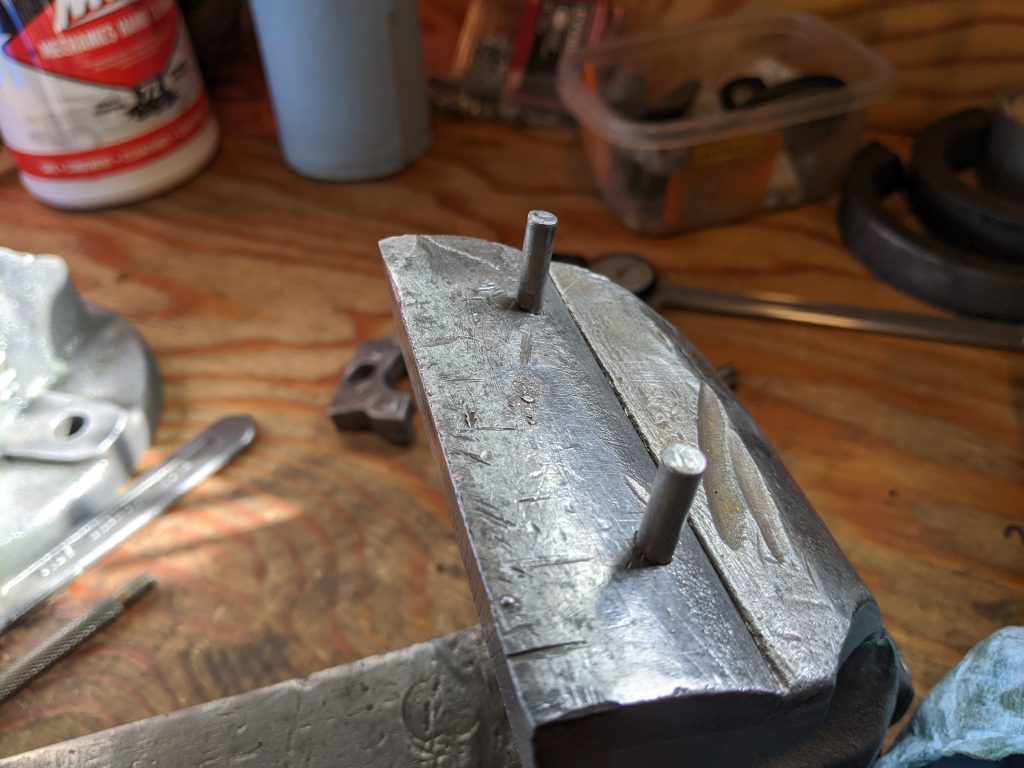
Jaw reinstalled with the new oversize retainer pins. Pins were a nice tight fit requiring some force to install but not enough to risk cracking anything.
New jaw retainer pins cut off near flush for finishing.
Retainer pins ground flush with a flap wheel.
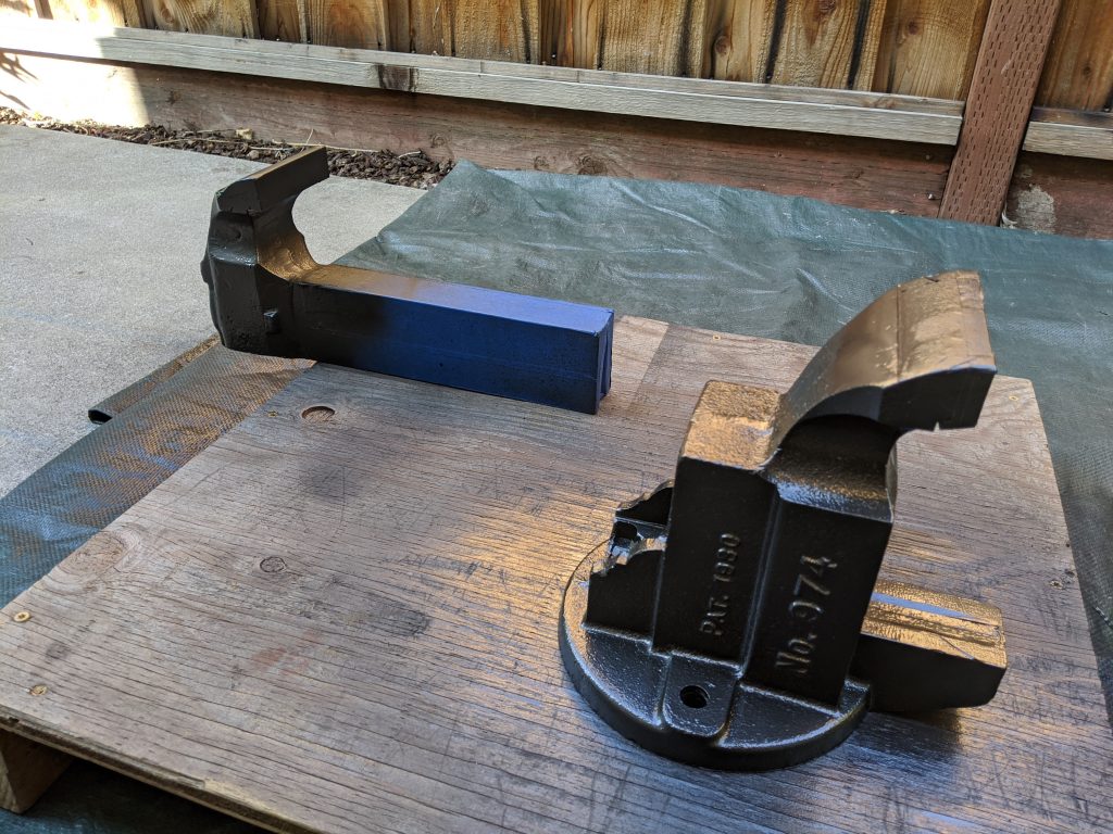
After carefully masking off the machined and sliding surfaces I took outside to paint. I used whatever hammered finish paint they had at the hardware store. I think the color was called “carbon”. Had the usual annoyances with the shitty can and nozzle design blowing spatters everywhere.
I cleaned up the sliding surfaces with a hand file and a whetstone. Didn’t go nuts on it, just made sure it was clean with no burrs.
I cleaned up the sliding surface of the moving jaw with a hand file and whetstone too.
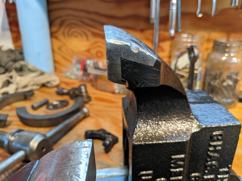
Finished jaw repair after painting and removing masking tape.
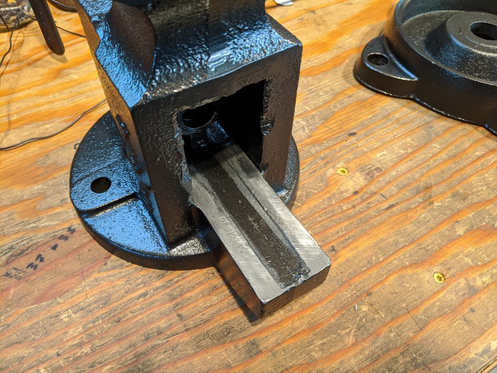
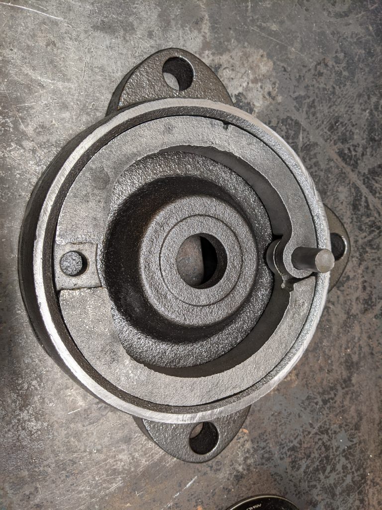
You guessed it . . . more hand filing and whetstone. This time the sliding surface where main body/receiver rotates on the base casting. This vise has a cool lock design that allows it to rotate and lock in an infinite number of positions. The two things that look like old drum brake shows? They pretty much are. The set screw from the top pulls up the expander wedge locking the vise securely in place. The main body/receiver is also drilled symmetrically so you can mount the set screw on the right or left side. My bench as a side rail on the right so I mounted the set screw on the left. The old vise was really difficult to lock and unlock in cramped quarters.
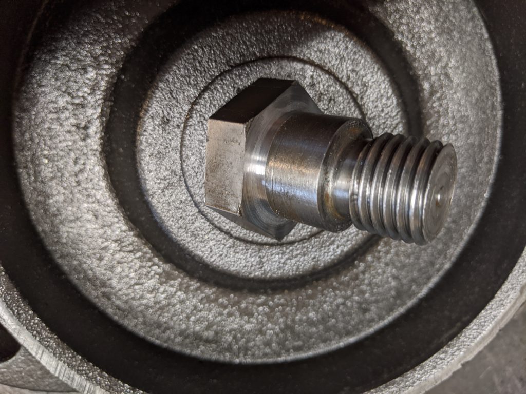
When rebuilding the vise I found that the main retainer screw could not be fully tightened without binding, preventing the vise from rotating on the base. It’s a shouldered screw so I removed some material from under the head so it could be bottomed without binding. Think I took off around .006″. Now it can be tightened fully. Yes, I know I could have bought some shims but I’m a man with a hammer (lathe) and this looked like a simple nail.
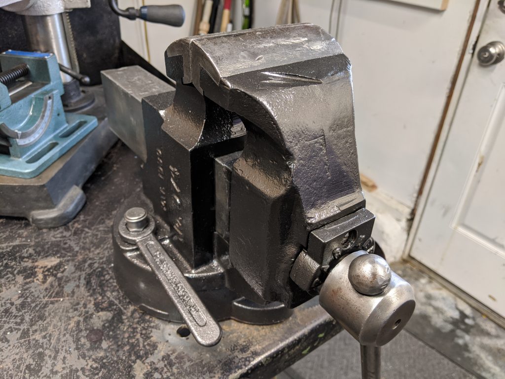
Completed vise. Looks great! Even has the original captured vise wrench.
Finished vise from the side. Ready for the next 100 years of service. Maybe my boys will have this one in their workshop after the worms have eaten me.

Bonneville Motor Prep: Rocker Box and Valve Springs

Hi All,
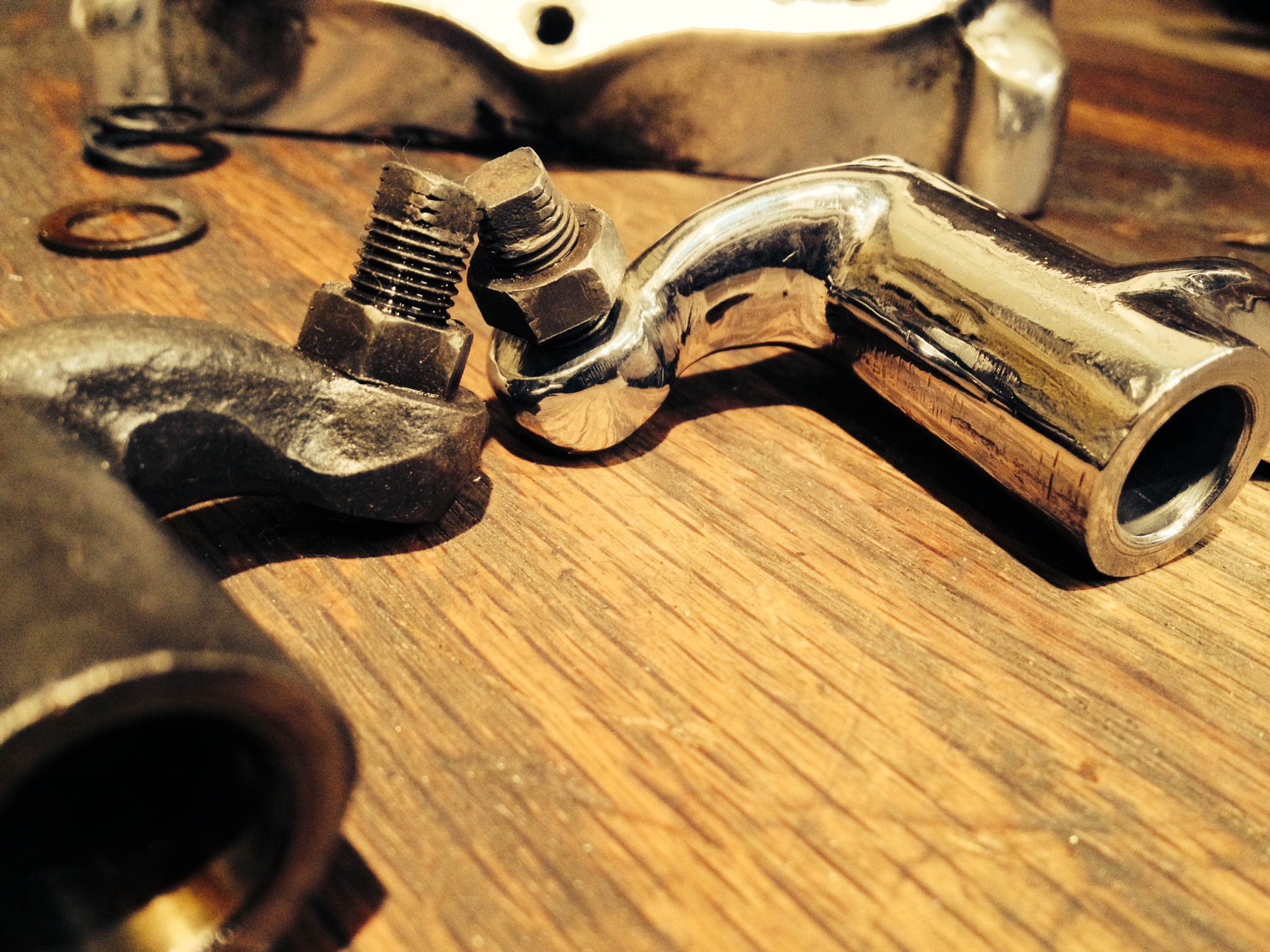
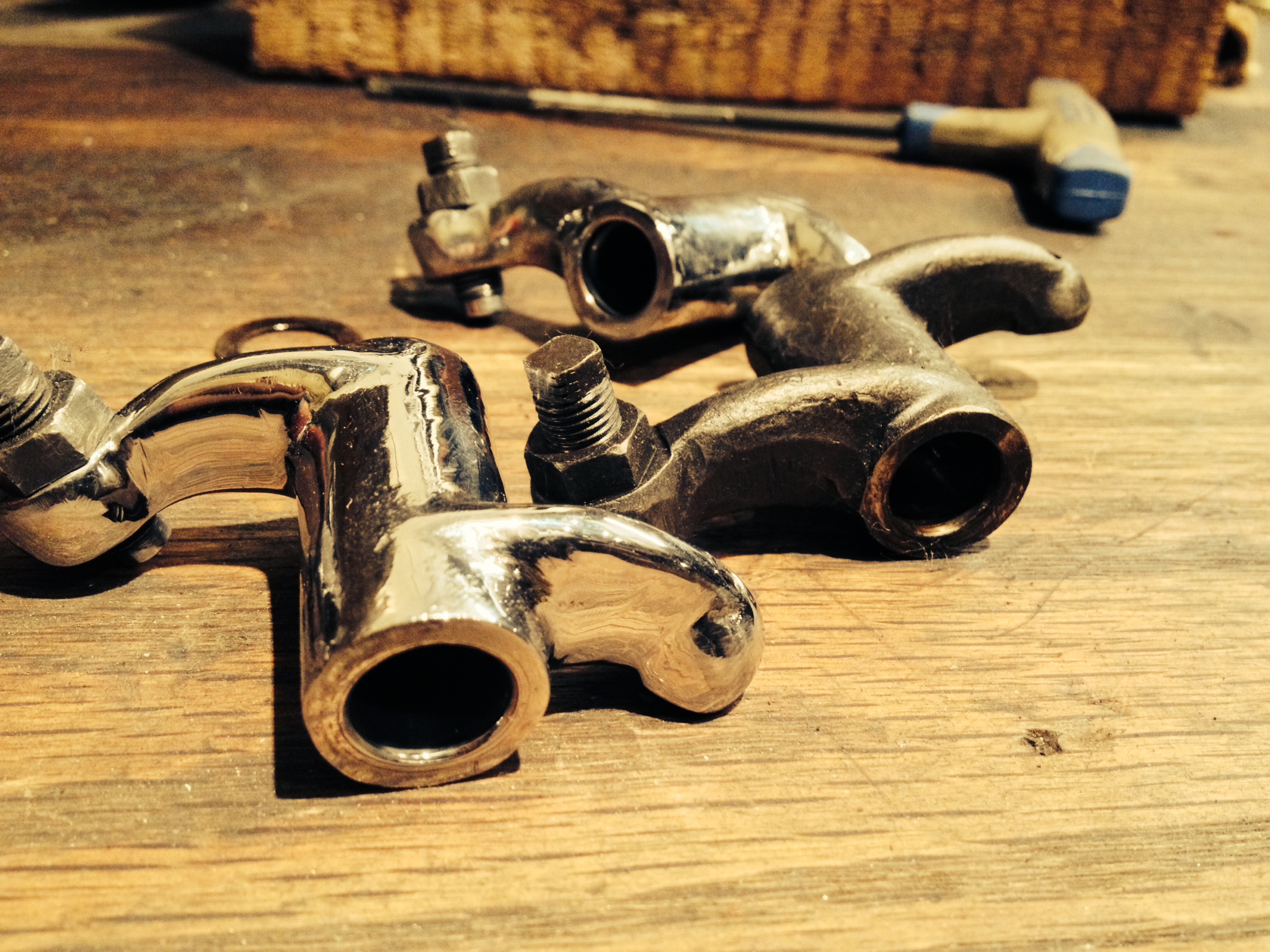
Ive returned from honestly “the best time in my life” out at Bonneville this year and and determined to get my BSA together to compete for next year. Been drafting a long post with lots of pictures from the trip but havent finished it yet. Stand Ready! Was out in the shop tonight working on the valve train of the race motor. Did a little lightening of the rocker arms, removing the casting flash and polishing out the stress risers. Pics tell the tail.

photo 2

Before and after

photo 3

I reduced the horizontal cross section and took some extra material off the outer most end at the valve.

My main goal with this is to lighten the valvetrain, this works by reducing the inertia of the rocker arms and helping prevent valve float,(we are running tight valve to piston clearance right?) I have already made some aluminum pushrods to replace the steel ones that came stock. Reducing the horizontal cross section does not effect the stiffness of the arm, the final shape is more oval, think of an I beam.

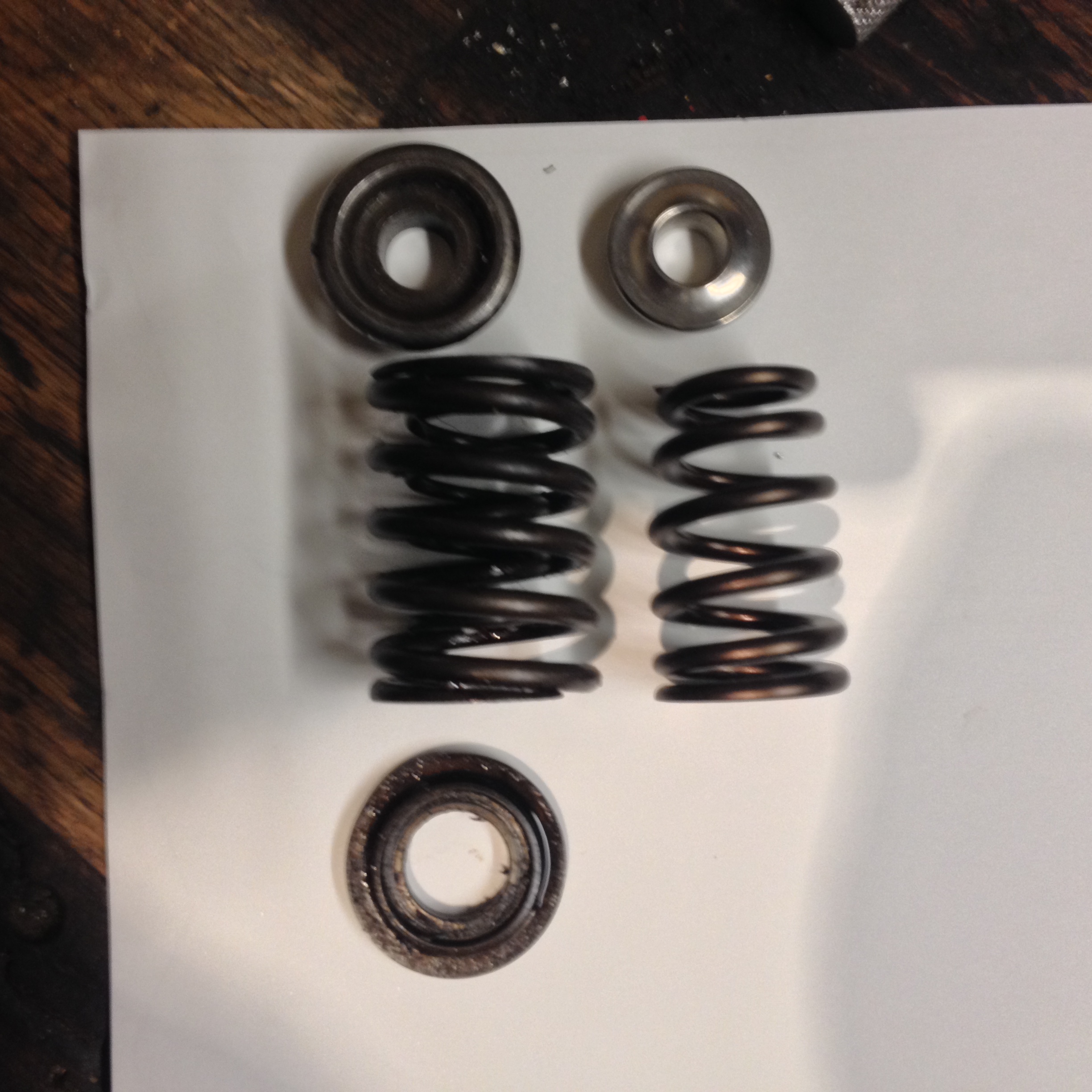
This brings us to the last piece of the puzzle, the valve springs. After much searching and spending a day on the phone and leafing through the comp cams catalog I settled on a ovate wire beehive spring. These represent the latest in spring tech only requiring a single spring as compared to the dual springs we are all used to. The wire and conical shape cancels out the bad vibes that will end my weekend, while allowing lower seat pressures.
If you think its wild that Comp would make springs for a 65 year old motor, your right, they don’t. The springs Im using are a combo of 4.6l 4 valve ford v8 springs, 5.7l dodge new Hemi Titanium retainers and valve locks for a small block chevy. I told you I spent the whole day in the catalog. The good news is these things are priced like your going to buy a whole set of 32 for that super sweet Ford 4.6 to go in your Mustang. Score for us 4 valvers.

I have not weighed this yet but the difference is considerable

I have not weighed this yet but the difference is considerable

Until next time
-DAN

Convert-O-Bike Project (Final)

Time keeps moving and I found myself a day away from Emmett’s birthday, needing to get down the shop to finish up. Still had the rear fork/axle to figure out, all the wheel bearings, the crank assembly, and finally, some cleaning up and polishing to do.

Got down there around 3p on Saturday, put some good music on and grabbed a big mug of coffee. I had a great time, which is what this is supposed to be all about. I was done by seven. Megan thought for certain that I’d be my usual maniacally obsessed self and get home at three in the morning. Sorry to disappoint.

Emmett loves it! I may have created a monster. He said nothing other than “Bike! Bike! BIke!” all morning after we gave it to him. His legs are about two inches too short to fully engage the pedals, but it’ll be no time at all until it fist him perfectly. He demanded that I push him all around the house while he steered, which I was happy to do.

Details of the build are in the pics as always. This was a fun one. Thanks for joining me.

Jason

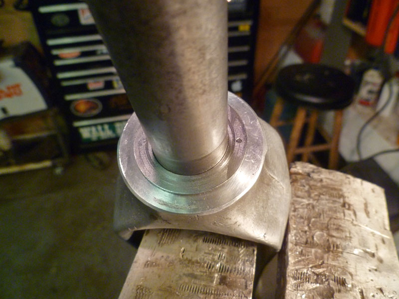
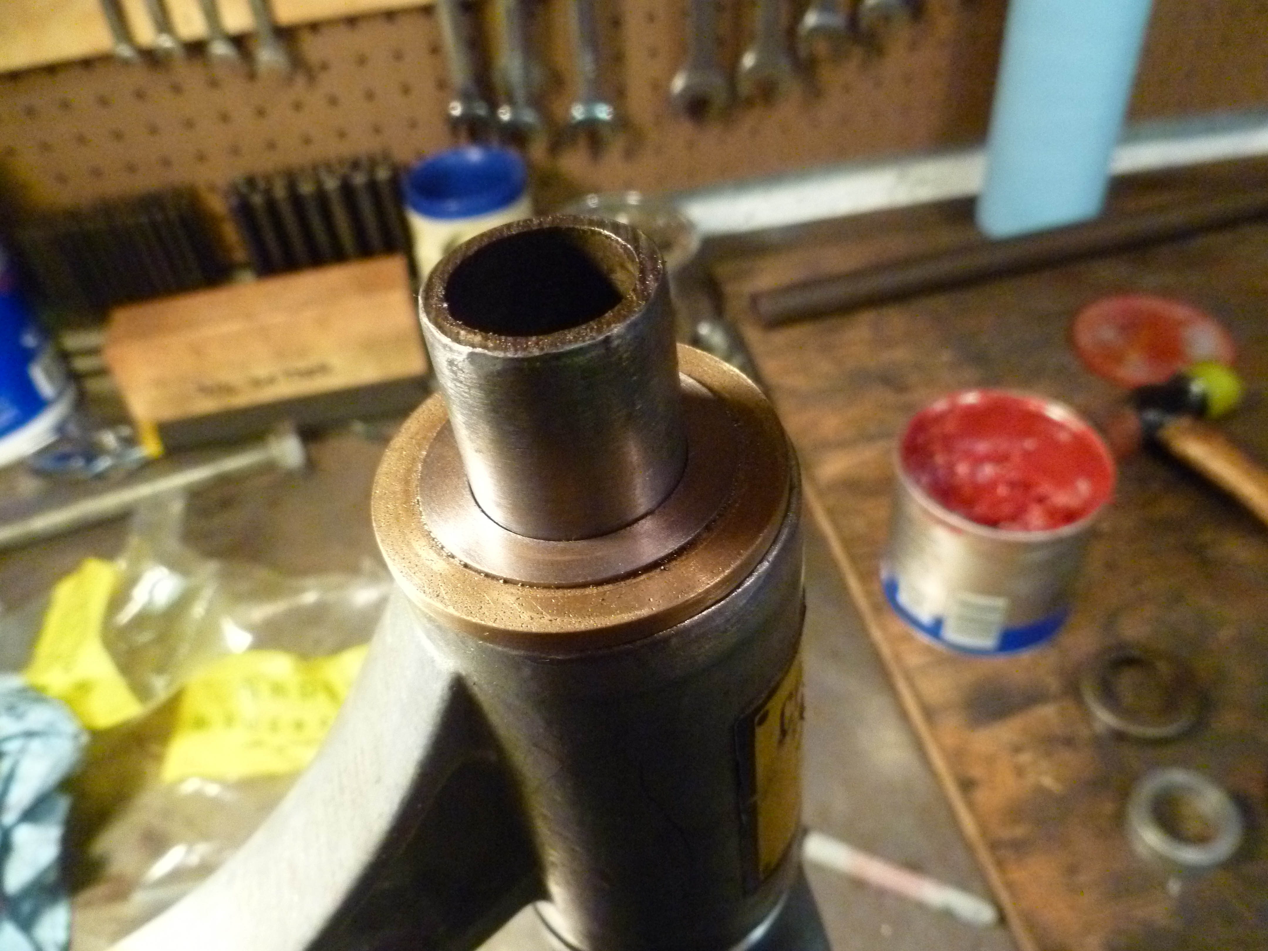
I embedded a hardened steel thrust bearing into a counter-bore in the bronze bearing between the fork and head tube so the original material would not get worn away. Here you can see it pinned in place so it doesn’t rotate against the aluminum shoulder.

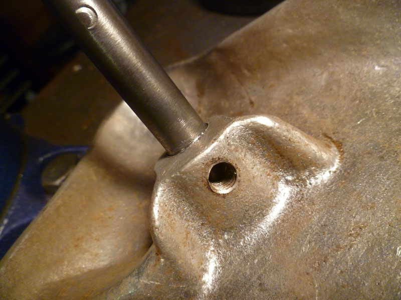
The seat post fit in the seat was hammered, leaving the seat wobbly and about to fall off. I built up the post with welding rod and turned it back down to a large enough diameter to press fit into the seat. The set screw remains although is now basically only for decoration.

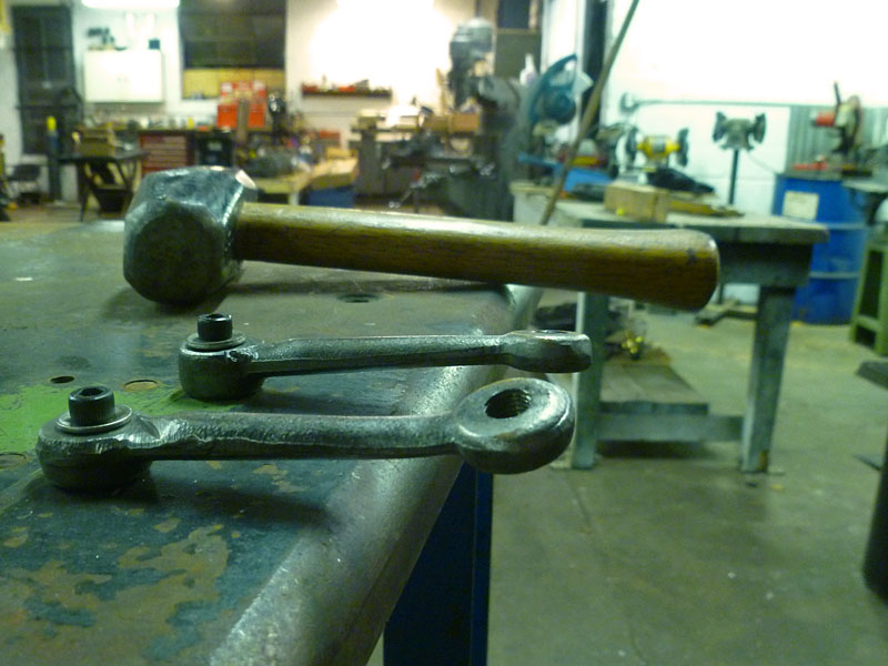
By this point, I was pretty certain this tricycle had been backed over by a car in someone’s garage. The cranks were twisted and bent pretty severely. Luckily we have a heavy duty jig/welding table in the shop. Bolted the cranks to the table next to each other so I could straighten them out with heat and a large pipe.

Continue reading

Convert-O-Bike Project (step 2)

After looking at the mess that was the head and steering parts I spent a day trying to figure out how to fix it. I really didn’t want to make a new stem or weld and reshape the existing one. Research into bearings (thanks, McMaster-Carr for having the best industrial supply business in the world) showed that no available ball bearings would fit the tight dimensions between the fork and frame head tube. I started thinking about how make up some bronze self-lubricating bushings instead. Couldn’t find any sizes that were plug-and-play so I made up a sandwich of two bronze bushings and a steel shim between them, pressed together concentrically. Worked great, if a little too much work for such a simple goal.

Once these bushings were made up, I counterbored one of them for a steel thrust washer so the fork crown (aluminum) wouldn’t get worn away over time. You can’t tell it’s even in there in the pictures. Clean.

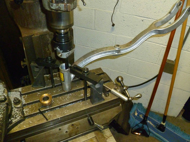
The head tube needed to be bored some for press fit of the bushings. Normally I’d have just turned the bushings down, but the frame had a big seam in the tube that would have prevented a proper fit. I mounted the trike frame to the milling machine table in kind of an oddball fashion, but it worked. I was too lazy to indicate the tube so just eyeballed the setup resulting in the bore being slightly eccentric with the original hole. Whatever. It’s a tricycle, not a track frame. It is silky smooth assembled with zero detectable play.

‘Til next time.

Jason

Frame mounted on the table for boring. Note the three-piece bronze bushing next to it.

Finished fit of fork in frame bushing.

The top collar needs to be machined down a little as the stack height has increased slightly. Easy enough.

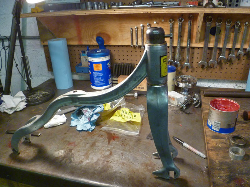
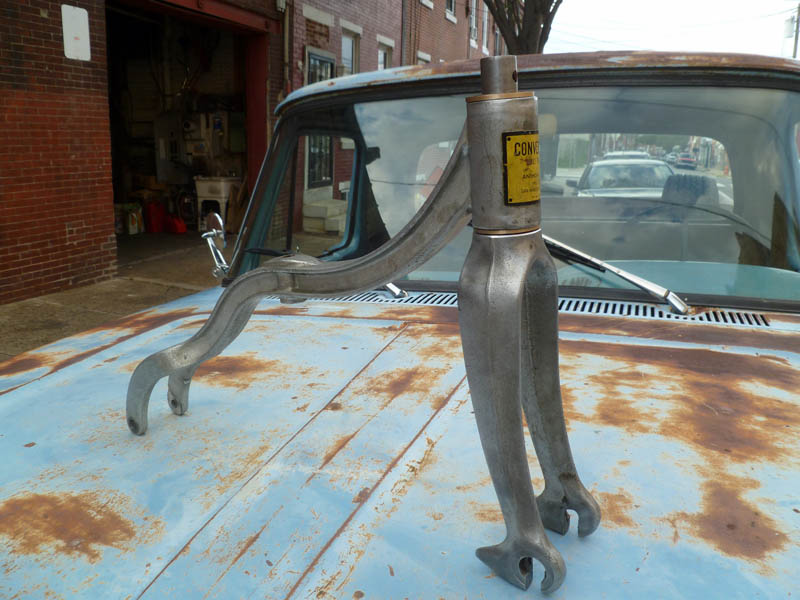
Finished frame and fork. Beautiful castings. Reminds me of the days I used to sweat high-dollar SE Racing framesets that lawn mowing money wouldn’t cover.

Previous installment . . .

Next installment . . .

Convert-O-Bike Project

It’s shop season again. Spent the summer moving to a new house and trying to squeeze in as many rides as possible. Now that things are cooling off, my mind is turning to interesting shop projects.

I found this tricycle for my two year old son Emmett about a month ago. He could not take his eyes off it. Once he climbed aboard, it was a real bear pulling him off. A week later I went back alone and bought it for him. I intend to rebuild it (it was pretty beat) for his upcoming second birthday in November. The shop wanted over $100 for it. I pointed out to him that almost every part of it was damaged beyond being functional. Every bearing was seized or rough, the head tube and fork had an inch of play as the bearings had long ago disappeared. The metal in metal areas was severely beat up and distorted. So I made the case that I am about the only customer that exists for this bike with both the desire and ability to fix it up and put it back into use. He could not argue with that logic and I ended up getting it for $70. After pricing bearings yesterday. . . I still overpaid. I don’t care, though.

The trike is an Anthony Brothers Convert-O-Bike. A little researched showed that they have been making them for over 50 years now. From a sticker on the underside of this one, it appears to be made in 1980, despite the ’50s design cues. If you look at the way the rear wheels attach, you’ll notice a forked connection on the main frame. This allows the rear axle to be replaced by a single wheel, converting the bike to a two-wheeler. Cool! The frame, wheels and most other parts are cast aluminum. Only the handlebars and seat post are steel. The grips are the only plastic on the whole bike. When I’m done with it, this bike will last for a hundred years and maybe my great grandkids will ride it.

I got down to the shop yesterday afternoon after going for a nice Fall motorcycle ride. It was a little tougher to get apart than I expected and damaged far more than I originally realized. It’s entirely disassembled, cleaned and inspected now. I have the various bearings on order. I still need to figure out how to bush/bearing the steering tube as the dimensions do not support the use of conventional ball bearings and I am unaware of how it was originally constructed. I think I’m going to make up some bronze bushings with thrust washers. We’ll see.

Pics of the break-down follow.

I can’t wait to see Emmett’s face when I give it to him.

Happy Fall,

Jason

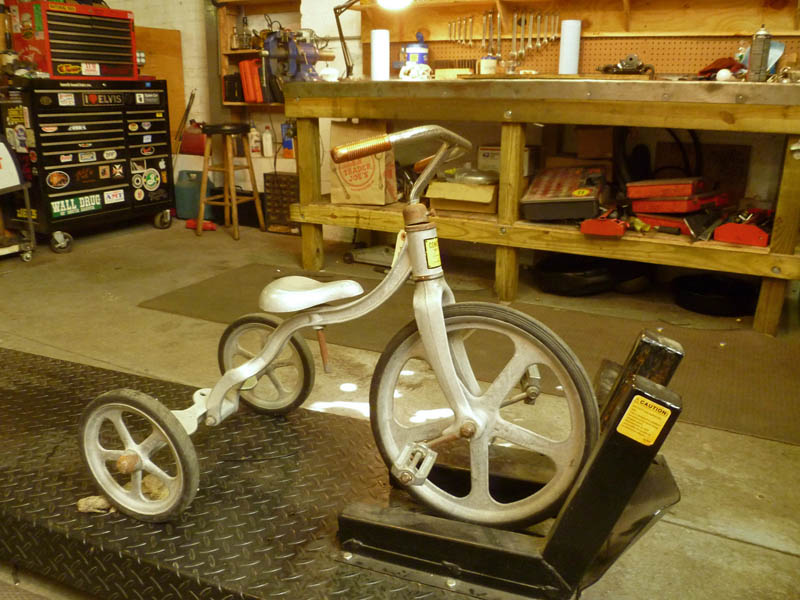
On the lift before dis-assembly.

Front end parts. The cranks were screwed on and welded. They needed to be cut to be removed. I was careful to leave enough metal on the spindle and cranks for reuse.

Close-up of front axle and cranks. The cranks are significantly bent and twisted. I’ll likely weld the ends to the edge of welding table and bend back straight.

Continue reading

Soap Box Derby Racer

So if you’ve ever read this blog before or met any of us, you already know that if it has wheels, we dig it. Better still, we’d probably like to rebuild it, change it or even make it from scratch. Not that motorcycles ever get boring, but it’s nice to mix it up from time to time.

We’re having a father’s day soap box derby on our block this weekend so Casey and I decided we should put something together for it. We talked about it sporadically over the last few weeks but didn’t actually get anything done. Last week, when we intended to build it, we sat around the shop sidewalk drinking beer with our friends and neighbors all night rather than actually accomplish anything. This was apparently much needed as we’ve all been working our asses off at our jobs lately and just didn’t have it in us to exert any effort on a project.

This left us with four days remaining to come up with something, sketch it out and build it. We started Tuesday night and ended up staying until 2am. We didn’t want to leave until we had a rolling chassis. I think that was an important decision, otherwise it might never have gotten finished.

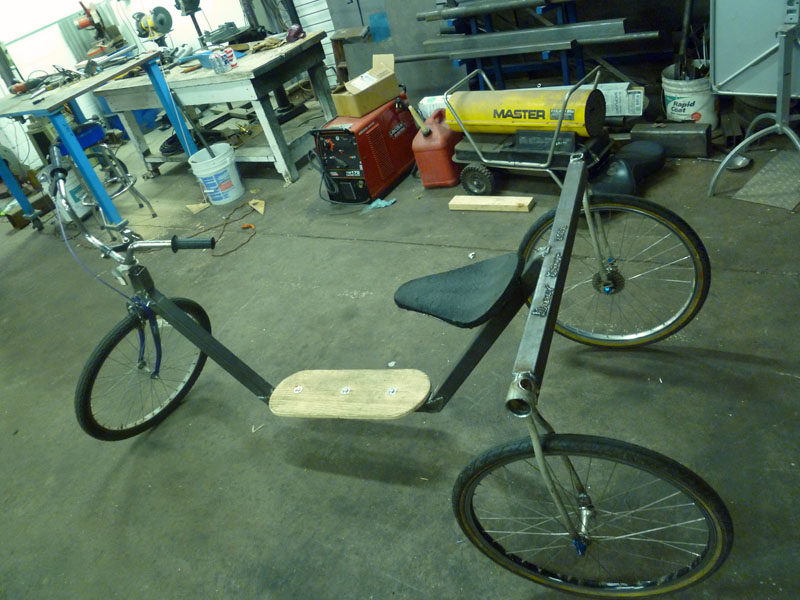
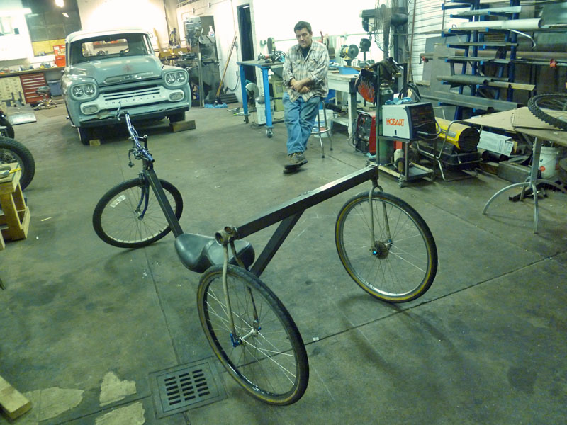
Our friend Al up the street donated an old beater bicycle to the cause and I snatched the wheels off my old Stump Jumper which hasn’t been ridden in years. Using a single length of square tube we had laying around, we created the entire frame. The bicycle was cut up to yield three forks: The original front fork, the rear seat stays serving as a pair and finally, the rear chain stays with the drop out tabs serving as a pair. We notched the square pipe after marking our angles, bent it upward into place and welded it shut. We flattened out the notches we removed to use as gussets on those joints.

Last night we added handlebars, a deck, a brake and welded a cantilevered seat the rear section so that two people could ride it. As this race is for neighborhood kids, we set it up so kids could sit on the deck with the adult on the seat doing the steering and braking. Not shown is a foot rest/wheel guard on the front to keep small feet out of the front tire.

We had a great time making this together and look forward to running it this Sunday.

Jason

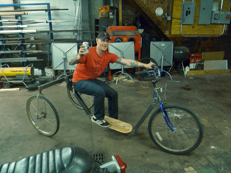
Finished product, less the foot rest we added at the very end.

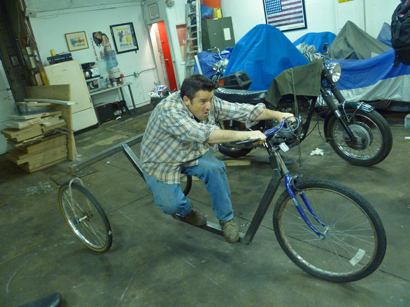
Casey doing his best speed pose on the rolling chassis.

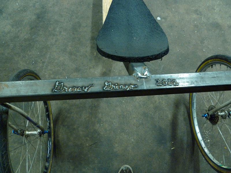
Gotta sign your work, right?

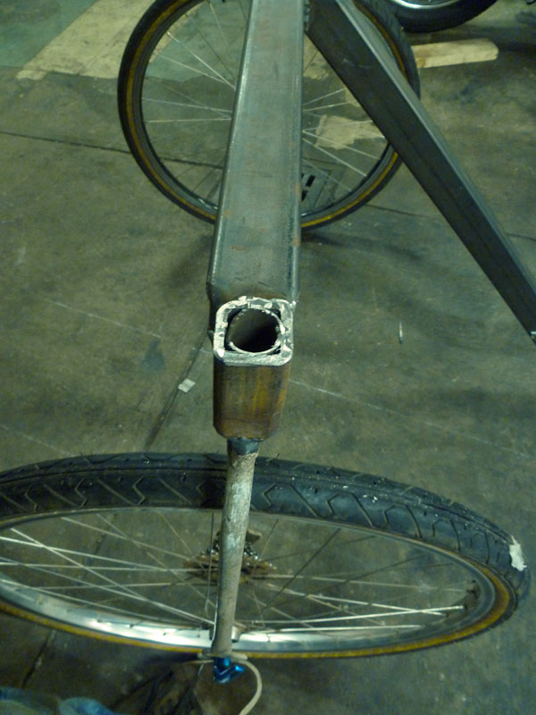
Bottom bracket and chain stays now serve as rear fork.

Seat stays serving as other rear fork. A little "smash & weld" going on to make it fit.

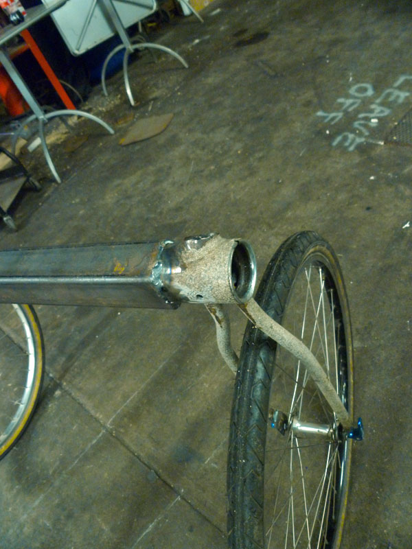
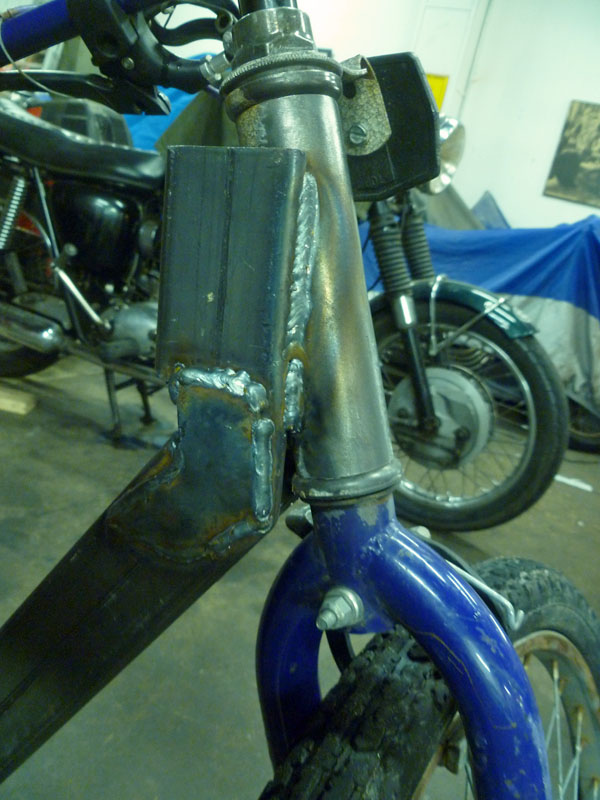
Frankenstein neck tube. Strong like bull!

Rolling chassis at the end of the first night. Still figuring out seating arrangement.

Wes on the finished cart. He hooked us up with handlebars and grips last night in addition to helping a bunch.

Fitting glide risers to an early springer

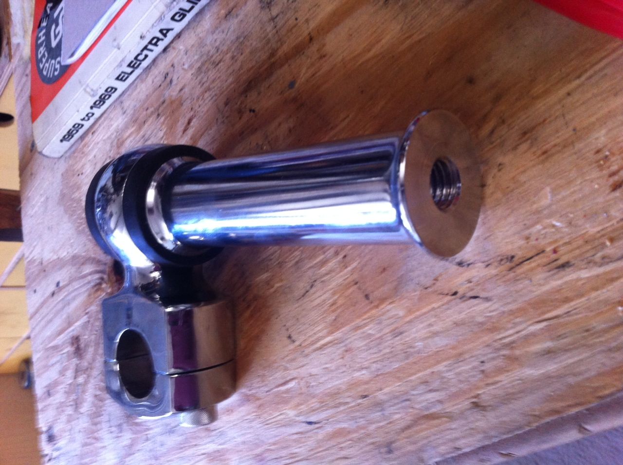
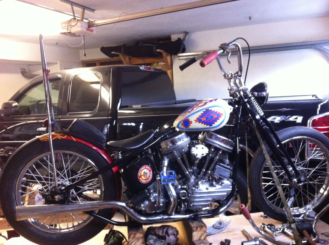
A few days ago Denny from california called me to bounce ideas about his current pan project. He has these flanders risers that he wants to fit to an early springer. Normally the springer top clamp has two ears that you would put dog bone risers on. He told me V-Twin used to make sell this but has called around and no one has had this for years. After 20 questions and some pictures I decided to turn these up for him.

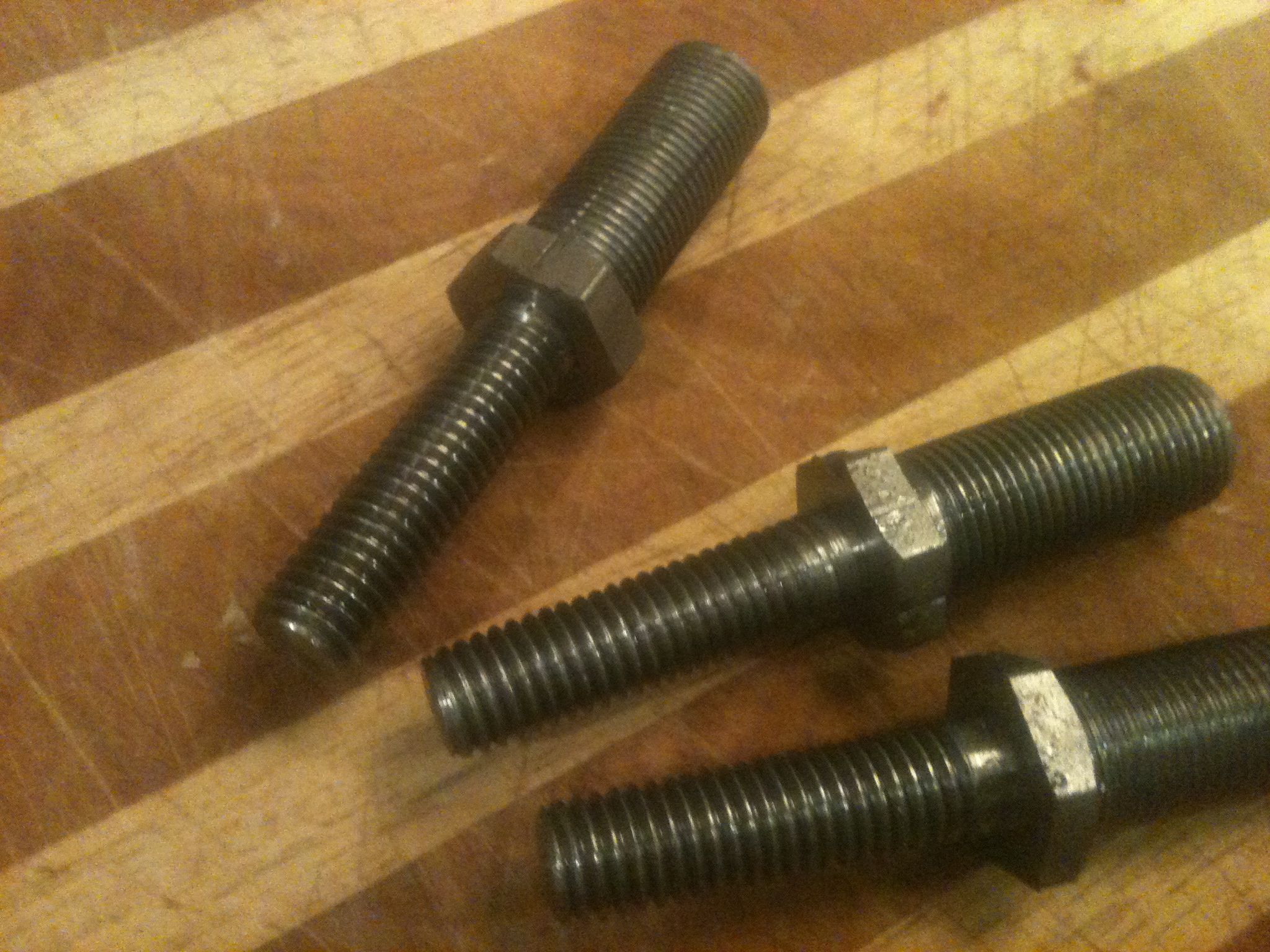
These are the risers, the bottom is threaded 1/2 x 13

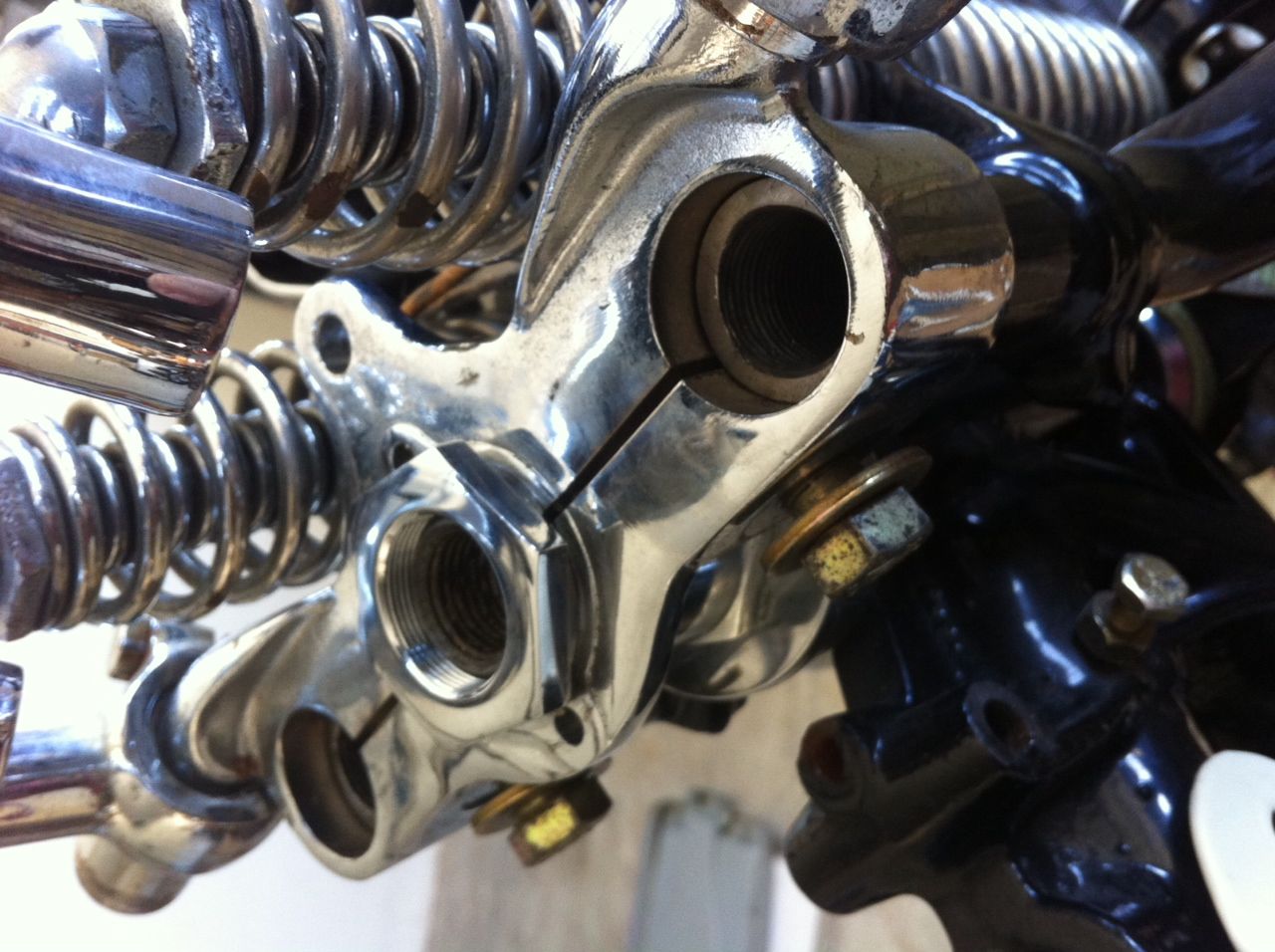
Its hard to see in there but the rear legs are threaded internal 3/4 x 16. The ID of the hole in the top tree 1" and the risers sit on top of the tree not in it. Also notice the ears with the dog bones mounted currently.

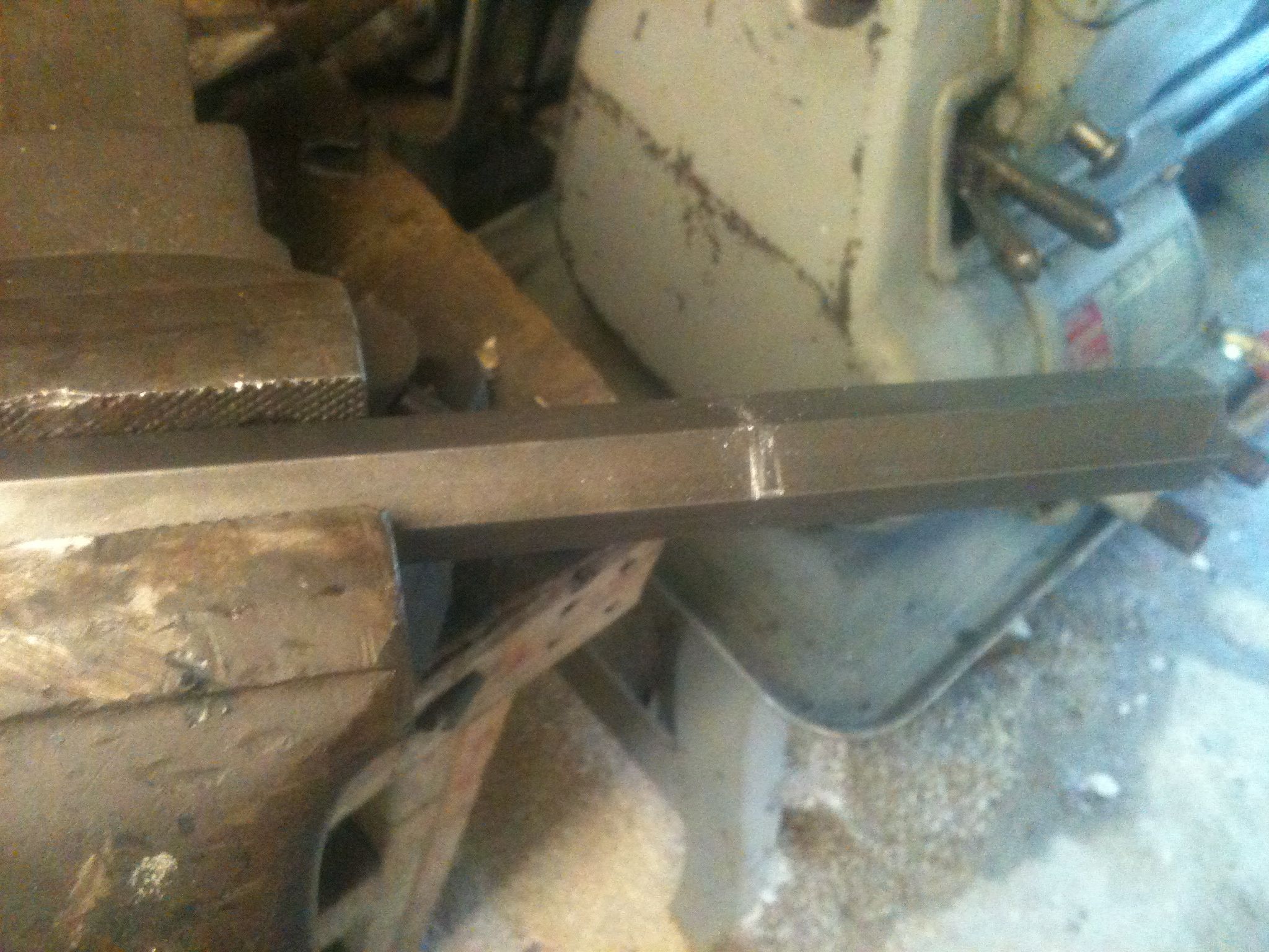
I ordered up the hex stock in 7/8 so it will fit in nicely inside the top tree.

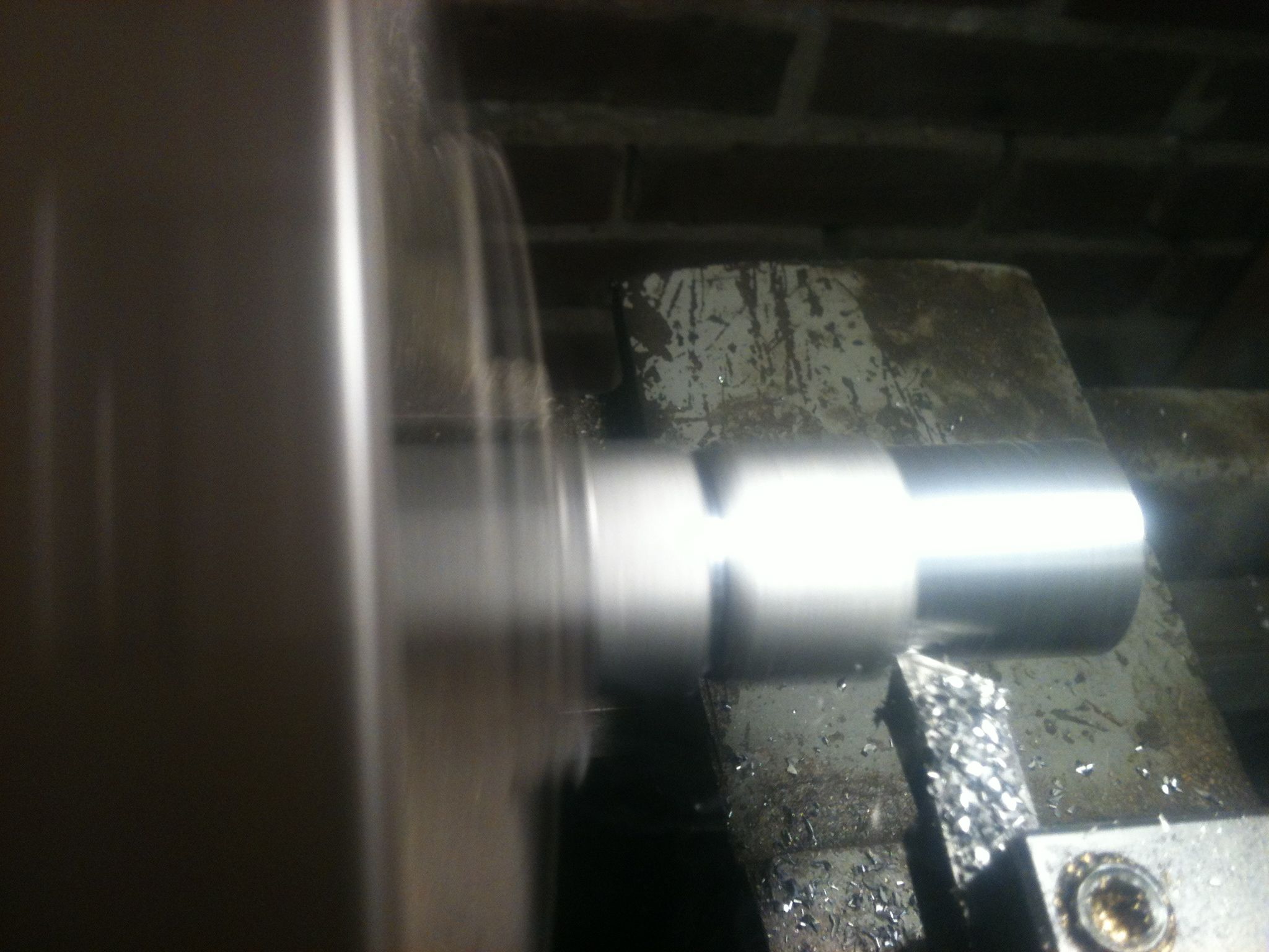
This is turning the side for the 3/4 thread to size, the half inch size has been done

RAW and almost finished.

Although Ive tried plenty of times I am never happy with the the threads when using the lathe in single point threading. Most of the time I start the threads with the lathe and get them almost to finished size, then run a die over them to finish. I did the same on these and it worked well.

Finished product, There are three because I wasn't real happy with the 3/4 threads on one

Here is the latest from Den

I bought plenty of extra stock so if any of you are looking for the same thing contact me dan@greasygringo.com And yes these are MAIDEN AMERICA

In Session: On Any Tuesday

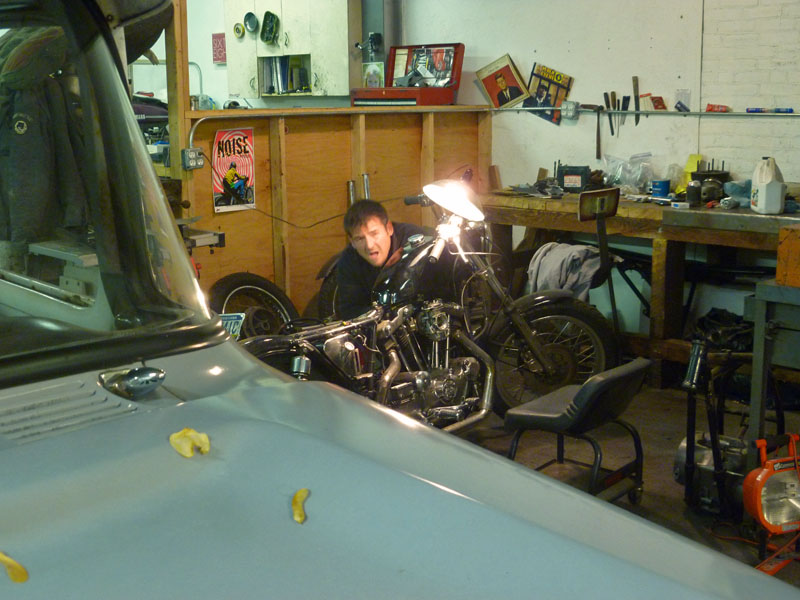
You might not see us around town much. Sure, here and there on nice summer evenings having a beer for a while. While all of us are good for a rave-up story and some beer-fueled antics from time to time, it’s really all about the metal. We like to build machines, improve them, figure out interesting problems. That’s where learning happens. That’s where interest grows and dues are paid.

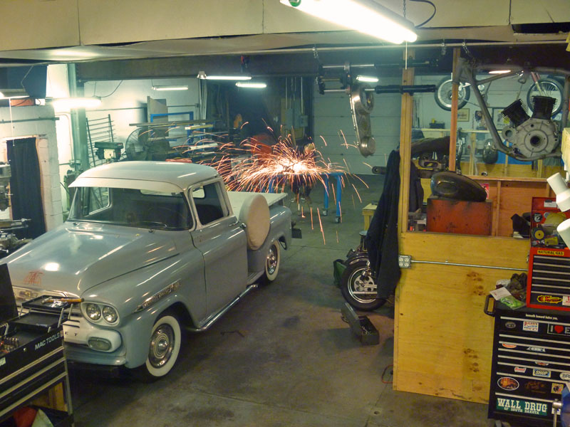
On any Tuesday night, it usually looks like this. Shop in session.

Jason

Bird's eye view. I've been rebuilding the door on the '59. All internals were shot.

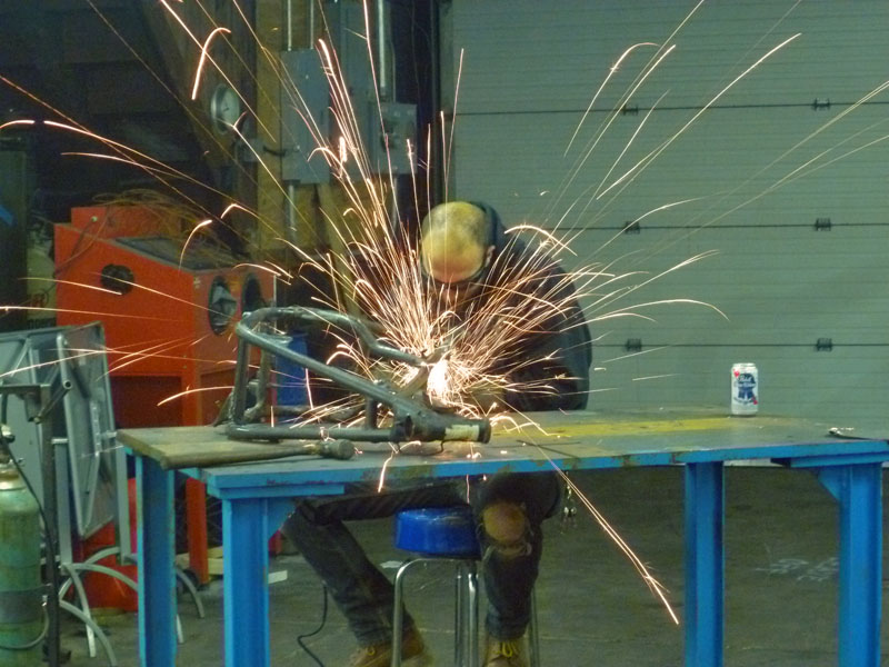
Dan tweaking the RD frame on the welding table

Casey getting his sporty ready for street duty

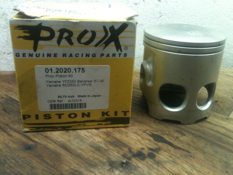
Using Banshee pistons in your air cooled RD350/400

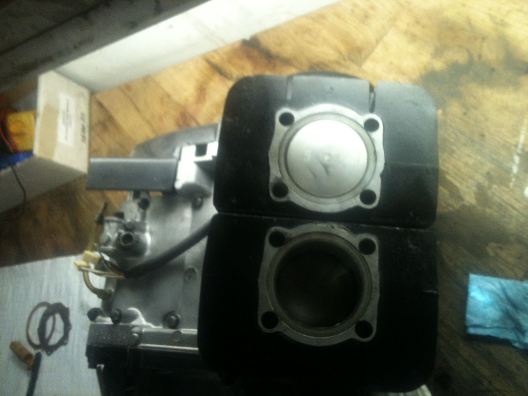
A few days ago my pistons and cylinders came back from the machine shop. Here is how they went together. The only company making true rd350 pistons now is wiesco big $$. Banshee pistons on the other hand are a dime a dozen and are available in a wider range of oversizes. With a small mod you can use the more plentiful banshee piston in the rd motor. Most places are charging $12-25 to modify this piston for your air cooled. Here were going to do it with no more than a few sharp jewelers files and some patience. There is a small tang under the piston ports you must remove. In the banshee intake there is a bridge in the center to allows this tang to ride. The rd has an open area here and the tang will catch on the bottom of the intake runner, break off and cause all sorts of damage  to the top end. I started by marking with a sharp pencil where I wanted to file off to. I CAREFULLY filed down to this mark just making contact with the scalloped areas to ensure it was flat. When you have it smooth all the way across, use a fine file to bevel the edge as not to catch on anything. As a side note I held this in my hand to do this NOT in a vise. It probably took me longer to write this post than modify both pistons. Make sure to thoroughly wash the pistons with hot soapy water to remove any contamination.

This is how the pistons come stock, notice the small tang on the bottom of the piston under the intake ports

Now with the tang removed

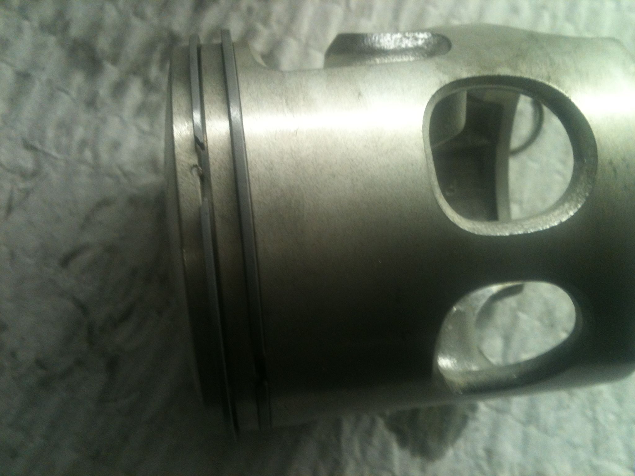
Now to install the rings, there are 2 pins in the ring lands to capture the rings and keep them from rotating into the ports. Look at the rings, notice that the end gaps have a section to correspond with the pins in the pistons. Install them this way. I should also mention you should check the end gaps by installing the rings only in the cylinders and checking the gaps according to the specs listed in your shop manual.

Notice the small pin in the ring land, this is to keep the rings from turning and catching the ports in the cylinders

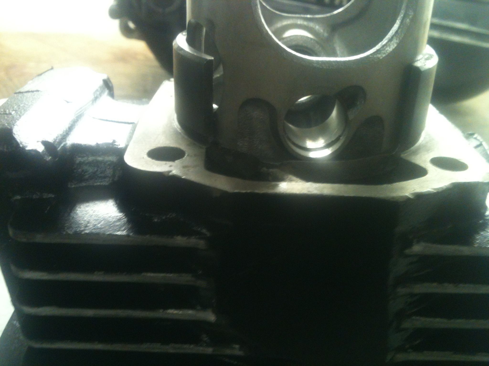
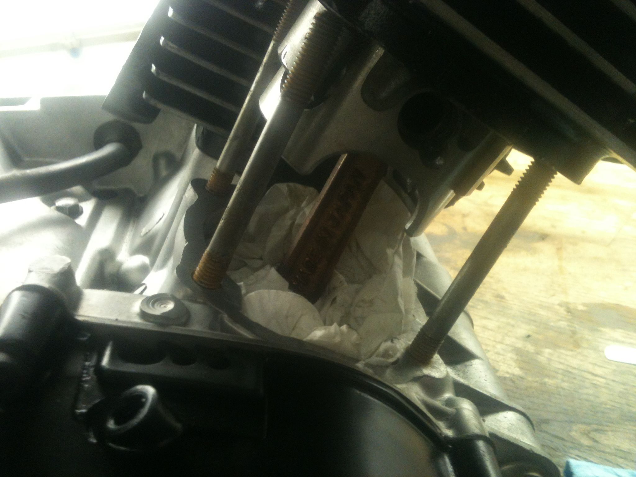
Since I was working alone this night I decided to try something to install the jugs more easily. It can often be hard to hold the jug and try to compress the rings and assemble it all even with a helper. I know some of you know what I’m talking about. This time I put the pistons in the jugs while they rested on the bench. This allowed me to only have to push the wrist pin in while suspending the jug with one hand, worked pretty well I thought.

Piston in just past the rings.

Paper towel to keep the circlip from falling into the case when I drop it

All together and at TDC

Later that night I put the heads on and did some measuring of the squish band, and started on some major rear suspension upgrades. Come back later in the week for more on that, promise you’ll be impressed.
-DAN

A Tour of the GG Shop

Every once in a while I like to walk around the shop with the video rolling. I like to look back at them later and see how much the shop has progressed or remember whatever projects were going on there at the time.

Nothing special. Just a slice.

Jason