Using Banshee pistons in your air cooled RD350/400

A few days ago my pistons and cylinders came back from the machine shop. Here is how they went together. The only company making true rd350 pistons now is wiesco big $$. Banshee pistons on the other hand are a dime a dozen and are available in a wider range of oversizes. With a small mod you can use the more plentiful banshee piston in the rd motor. Most places are charging $12-25 to modify this piston for your air cooled. Here were going to do it with no more than a few sharp jewelers files and some patience. There is a small tang under the piston ports you must remove. In the banshee intake there is a bridge in the center to allows this tang to ride. The rd has an open area here and the tang will catch on the bottom of the intake runner, break off and cause all sorts of damage  to the top end. I started by marking with a sharp pencil where I wanted to file off to. I CAREFULLY filed down to this mark just making contact with the scalloped areas to ensure it was flat. When you have it smooth all the way across, use a fine file to bevel the edge as not to catch on anything. As a side note I held this in my hand to do this NOT in a vise. It probably took me longer to write this post than modify both pistons. Make sure to thoroughly wash the pistons with hot soapy water to remove any contamination.

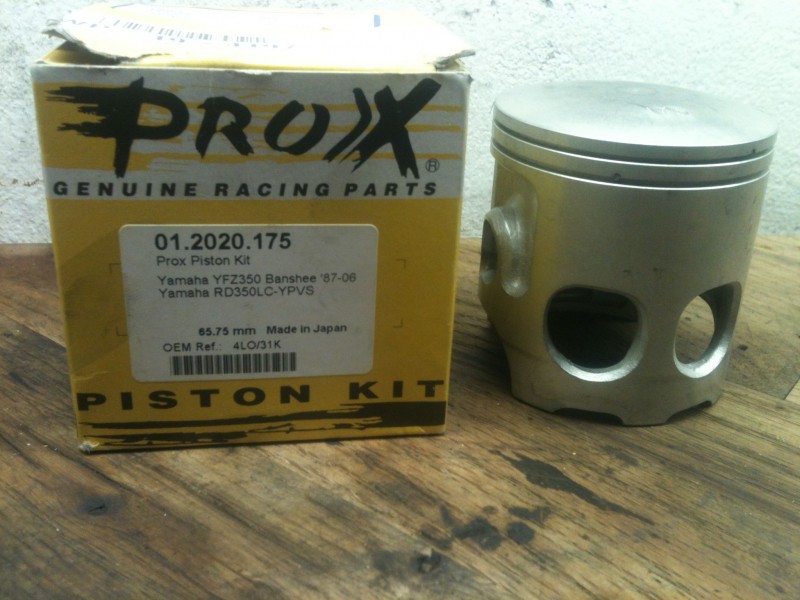
This is how the pistons come stock, notice the small tang on the bottom of the piston under the intake ports

Now with the tang removed

Now to install the rings, there are 2 pins in the ring lands to capture the rings and keep them from rotating into the ports. Look at the rings, notice that the end gaps have a section to correspond with the pins in the pistons. Install them this way. I should also mention you should check the end gaps by installing the rings only in the cylinders and checking the gaps according to the specs listed in your shop manual.

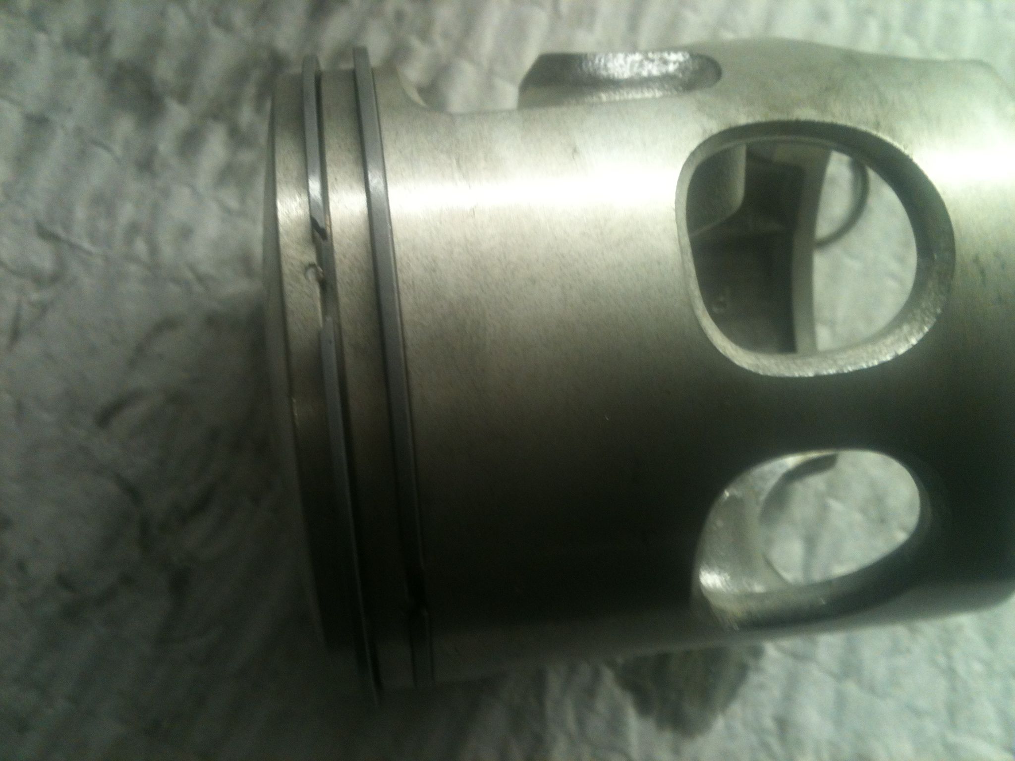
Notice the small pin in the ring land, this is to keep the rings from turning and catching the ports in the cylinders

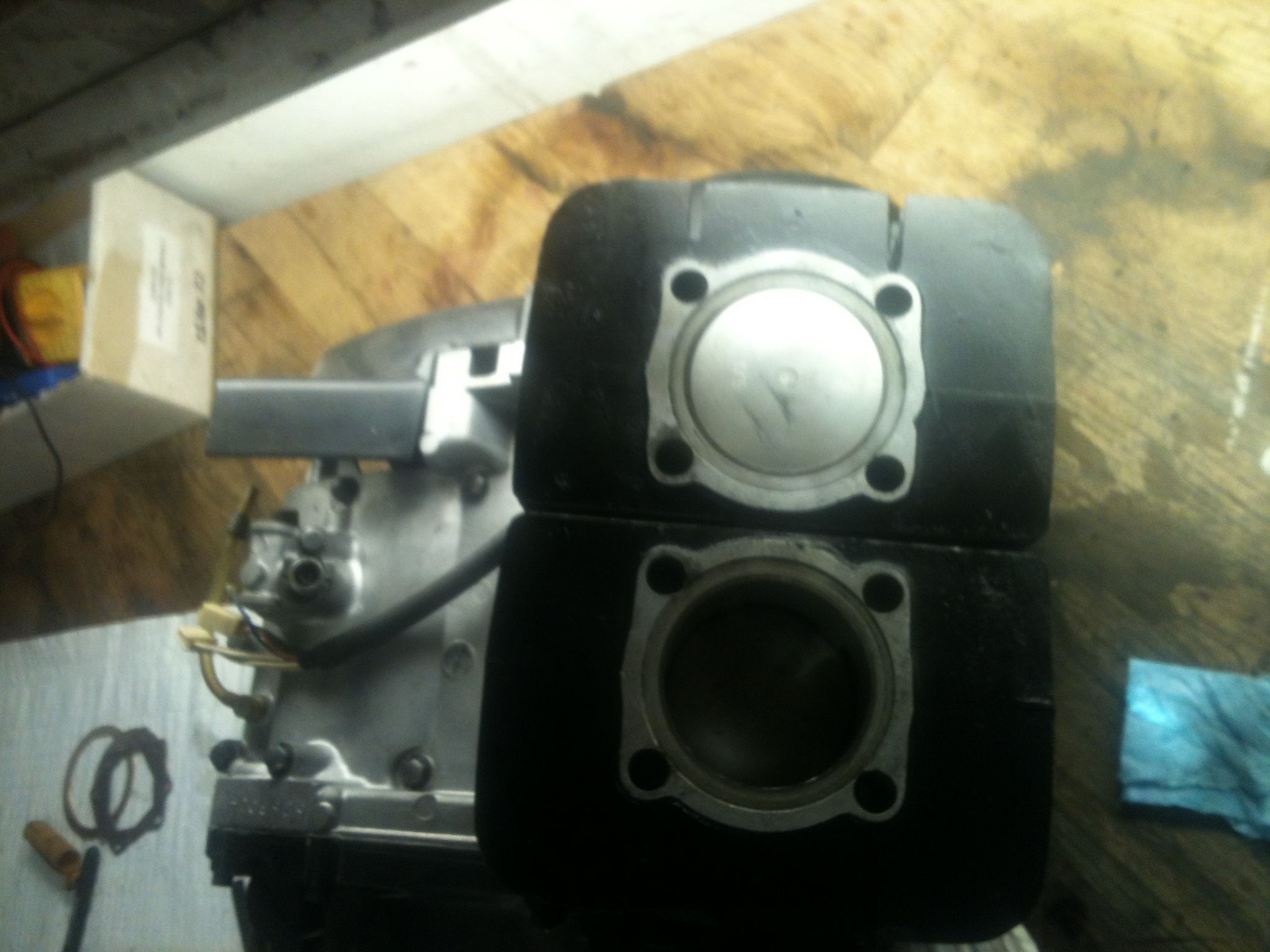
Since I was working alone this night I decided to try something to install the jugs more easily. It can often be hard to hold the jug and try to compress the rings and assemble it all even with a helper. I know some of you know what I’m talking about. This time I put the pistons in the jugs while they rested on the bench. This allowed me to only have to push the wrist pin in while suspending the jug with one hand, worked pretty well I thought.

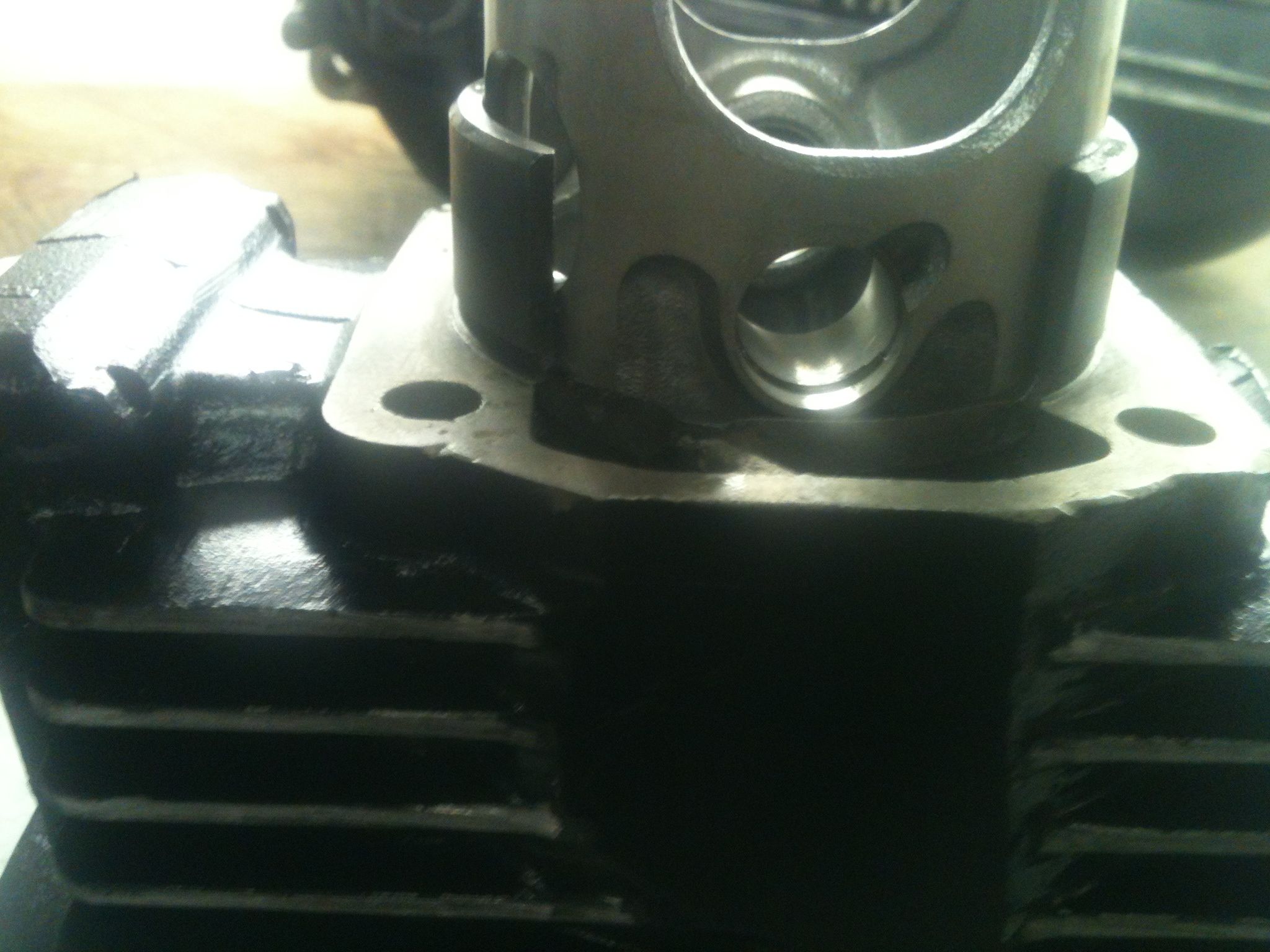
Piston in just past the rings.

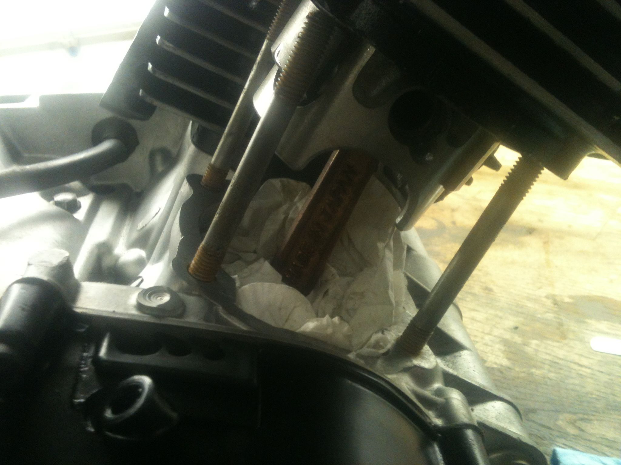
Paper towel to keep the circlip from falling into the case when I drop it

All together and at TDC

Later that night I put the heads on and did some measuring of the squish band, and started on some major rear suspension upgrades. Come back later in the week for more on that, promise you’ll be impressed.
-DAN

Some Old Pics. . .

Spring time and the smell of gasoline and old grease really stirs up the memories for me. Was thinking yesterday about past bikes and the excitement of spring coming. Living up in Rochester, NY for years where’s there only six warm days a year really makes you appreciate the coming warmth. What better way to celebrate than to go for a ride?

These are randoms from the pile/mess that exit on my computer.

Enjoy.

Jason

Kevin's panhead in from of my apartment in Soho. Around '98.

First bike I ever built. I was still in college. Build it in my back yard. '92

New Year's day ride in the East Village. '99. My old Triumph. You might recognize the red & black bike too.

Times Square about ten years ago. I used to give everyone who visited tours of the city.

11th Avenue outside of Red Rocks. Taken by English Don.

Bear Mountain. Our favorite nearby destination when I lived in NYC. Around '97.

One of my first mentors. Spencerport, NY. Maybe ten years ago.


Continue reading

Not to Long Ago

With all this machining and making parts as of late, got to me thinking about the places that used to do these things on the regular and how there disappearing. Soon we will only have ourselves and the cottage industry to rely on to keep the machines we love on the road. I ride by this now abandoned building every time I go down to the shop. Reminds me of a time about 12 years ago I had needed a carb serviced apon moving to the city. I asked around south philly where I was living at the time and the general consensus was North Philly’s Palacio Carburetor. This was an old clapped out 2 bbl on a 74 Plymouth Valiant. After riding about 60 blocks on my bicycle I was there. Despite all the windows on the side of the building when you entered it was like a cave in there. There were boxes of carb cores and ac compressors piled to the ceiling blocking off all light. I was told by the old guy behind the counter that it would be ready in a week or so. Week goes by and I get a call from them to pick it up. A half a day bicycle ride later I was there again. The old guy and I talked shop a while and I asked him a about the 100% engine tested on his sign. He gave me the old “come here kid” and we meandered through hallways with walls of parts and carbs to a back room with an old flathead 4 on a test stand. He asked me for my carb out of the box that he had just given back to me.
This intake manifold on the flatie had a big square sheet metal box on it where the carb would go. Looked to have been gas welded 100 years ago. He reached up to a wall of adapter plates made of mahogany and put the 2bbl one on and set my carb on top. There was some kind of quick action ratcheting lever arm to press down on the carb body to make a seal. He pushed on a fuel line and fires that old flathead 4 right up. Cool.
After that I brought it home and put it on the Valiant, It ran great after that, I can’t remember so well now but I think they re-bushed the shafts and changed out the jets and powervalve. It makes me wonder where all the industry has gone. Please feel free to share your stories in the comments below.
-DAN

From when stuff was worth rebuilding

9th and Allegheny

4LS to Roadholder Fork (part 3)

Managed to squeeze in one more session last night before heading out for vacation in DR Friday in the wee hours. You know I’ll be thinking about this project next to the pool with a drink in my hand. Can’t turn it off. Ever.

I walked into the shop last night at 8:30p after a 15hr day traveling and working. I was on the lathe making chips by 8:33p.

This is the original Suzuki axle that belongs to the hub/brake. Research showed that most folks used the Norton axle for this modification. Well, I don’t have one. Plus, the Suzuki axle already has the correct dimensions for the bearings, which is an important fit. At the end of last session, with Young Dan and Mika’s input, we came up with a plan to turn down the pinched section of the axle to match the right right fork leg. We also decided to bore and bush the left leg to match the smaller axle diameter and face it off so the brake plate and heavy washer and main nut will have a large uniform engagement area to better handle the increased braking loads and resist deformation.

I didn’t have a suitable piece of steel to make the bushing so I used a piece of bronze bushing stock I found in my scrap bin. I never throw metal away. I’m the type of weirdo that will pick nuts and washers up off the street and pocket them for later deposit in the junk barrel. Don’t laugh. I almost always come up with a suitable piece of material.

Step by step below in pics, as usual. Only had a cell phone last night, so pics are crappy.

Bonus question for the observant: One of the fork legs requires one more machining operation. Be the first to name it and we’ll send you sweatshirt next time we make a batch.

Adios, mi amigos.

Jason

Pinch-side fork leg before modification. Note the crack. I don't think it's in a critical area considering most of the load is borne nearer the pinch boss.

Locating the fork leg in the milling table vise is a hassle and takes time to get right. I decided to try a new approach. I made an arbor/fixture out of aluminum such that one side fit the collet and the other a slip-fit in the fork axle boss. Chuck the arbor, install the fork leg and locate the table and vise to the suspended leg. Tighten down and check that the arbor travels freely when you raise and lower the quill. Worked like a charm! Had to set the leg three times last night for various steps and this took a minute each time.

Suspended fork leg on the fixture/arbor made for this purpose.

Boring the axle boss on the mill. This old girl is in such great shape the automatic down-feed and shut-off still work flawlessly. These features are usually broken on old manual mills. I wanted the bushing to have sufficient wall thickness to that it would not deform when pressed in. I also wanted a uniform hole for the press-fit. Otherwise I would not have modified the fork leg.


Continue reading

4LS to Roadholder Fork (part 2)

I’m on a roll here! Three shop sessions in a single week. Feast or famine.

I’ve been thinking this project over in my head every day and considering things I may have overlooked or misunderstood in earlier sessions. That’s the way I work. Constantly confirming observations and reassessing approach. I catch a lot of mistakes and omissions this way. Last night I tested a few initial assumptions with some layout blocks and squares. First, that the protrusion of the fork axle bosses was equal on both sides. It wasn’t. Second, that the hub and brake plates were symmetrical. They are despite different casting features on the speedo drive side. Lastly, that material must be removed symmetrically from fork leg pairs and brake plate pairs. Not true. An artificial constraint. Really, only the total amount of material removed the combination of brake plate and fork on each side must be same (less any symmetry difference in the legs) in order to leave the hub centered in the fork.

This last realization allowed me to save more material around the speedo drive boss and leave it in working condition. There was room to cut the fork back further on the speedo side allowing me to cut back less on the corresponding brake plate. An important finding.

So I got busy after getting home from NYC at 8pm. Getting up for work at 5:30a, traveling to the city to work all day, then driving back to Philadelphia makes for a long day. Didn’t stop me from heading directly to the shop though.

After removing another .110″ from the speedo-side fork leg, I next set about figuring a way to fixture the brake plates in the lathe or mill for final material removal. I preferred to use the lathe if possible as it’d be much easier to ensure the faced surface was perpendicular to the axis of the axle. There was no way to grip the brake plates with my 10″ swing lathe (due to no suitable protrusions, not diameter) so I decided to make an arbor out of some steel round stock, turned down to a press fit in the brake plate sleeve. This worked great. When done, I just pressed the arbor out on the hydraulic press. I also faced off the arbor so that I could use the depth mic to quickly and accurately measure material removed from the brake plates while still fixtured.

It all worked out and I got much more done than expected. The modifications are complete and the hub/brake setup slipped between the fork legs perfectly!

Next step is to modify the axle and fasteners to fit this Suzuki axle to the Norton fork. We came up with a plan late last night. Details in coming installments. After that, design and creation of brake stay straps and a fork brace to run between the fender bosses. Then finally, to polish and paint it all up for a proper appearance on JW’s fine Brit racer.

Jason

The mouting arbor pressed into place on the brake plate. Fit is .001" interference. The arbor is shouldered. The plate indicated true once mounted in the lathe chuck.

The machined arbor face used to measure material removed. Using a depth micrometer dropped from the boss (in red) a reading can be taken quickly and accurately.

Removing material on the lathe. Note the steel insert feature on the brake plate.


Continue reading

A Tour of the GG Shop

Every once in a while I like to walk around the shop with the video rolling. I like to look back at them later and see how much the shop has progressed or remember whatever projects were going on there at the time.

Nothing special. Just a slice.

Jason

Using an EZ-Out and Properly Installing a Heli-Coil

Found myself with a free afternoon in the shop today and put some more time in on the Suzuki 4LS hub to Norton Roadholder fork conversion. After pulling all the parts out of the kerosene tank from soaking all week, I started to fix up the fork legs.

The one leg had a broken off stud in the fender mount boss that looked like it’d been there for a while. Rusted in pretty good and a nice jagged break indicating it took a lot of force to snap. Usually that means it’s stuck pretty good. The other leg had a brake stop boss that needed to come off. Got both done today but I’ll save the latter for another article. As the new setup will use these fender mount bosses as brake stay mounts, I thought setting them up for a larger stud (1/4″ – 20) and installing steel thread inserts would be wise.

This article will show you how to remove a broken fastener from a blind hole using what is commonly known as an “EZ-Out” or screw extractor. It will also show how to properly install a helical thread repair insert, or Heli-Coil which is the primary manufacturer of these style inserts. I used a milling machine to do the drilling and tapping for the thread repair, but this certainly isn’t necessary. Since I have one, I’m gonna use it where it helps me. You could just as easily do it with a hand drill in a vice (with a little care) or better yet, in a drill press. Drilling and tapping in a fixed setup like a drill press or milling machine ensures the holes are drilled square and the tap starts correctly.

I’ve heard plenty of people say that helical insert thread repairs are no good or don’t last. Bullshit. When installed correctly (I suspect many that say they don’t work are ham-fisters) they will be stronger and last longer than the original threads. Many manufacturing applications use them as standard equipment, not just for repairs but for new products.

There are sleeve style inserts for thread repairs too. They have strengths and weaknesses just like helical inserts. Some fixes may lend themselves to one or the other, but that’s a subject for another day. Both will perform beyond adequately when installed with care.

I had a great day listening to old blues and gospel music with the early spring sun shining in my workshop window. Just me and an interesting project. Hope you find this helpful.

Jason

The first step is to grind or file down the broken screw so you have a nice flat surface to start with. Be careful not to gouge up the surrounding area too much. After it's ground flat, you can center punch the broken screw so the drill will not skip off.

Carefully drill a hole in the center of the broken screw. The largest hole you can drill without going into the surrounding material is best. This serves two purposes: 1) Allows use of a larger screw extractor that can take more force 2) Thins the screw you're attempting to remove, exerting less force on the hole in which it's stuck.

After choosing the extractor that fits the hole you just drilled, place it in the hole and smack it forcefully with a hammer so that it bites into the screw. Be careful not to shift the extractor or put any lateral force on it after you've "set" it into the screw. You can see in the picture how the sharp edges on the extractor bite into the screw and are twisted counter-clockwise such that it grips better as it is turned outward.


Continue reading