Rebuilding an 80 year old Parker 974 vise

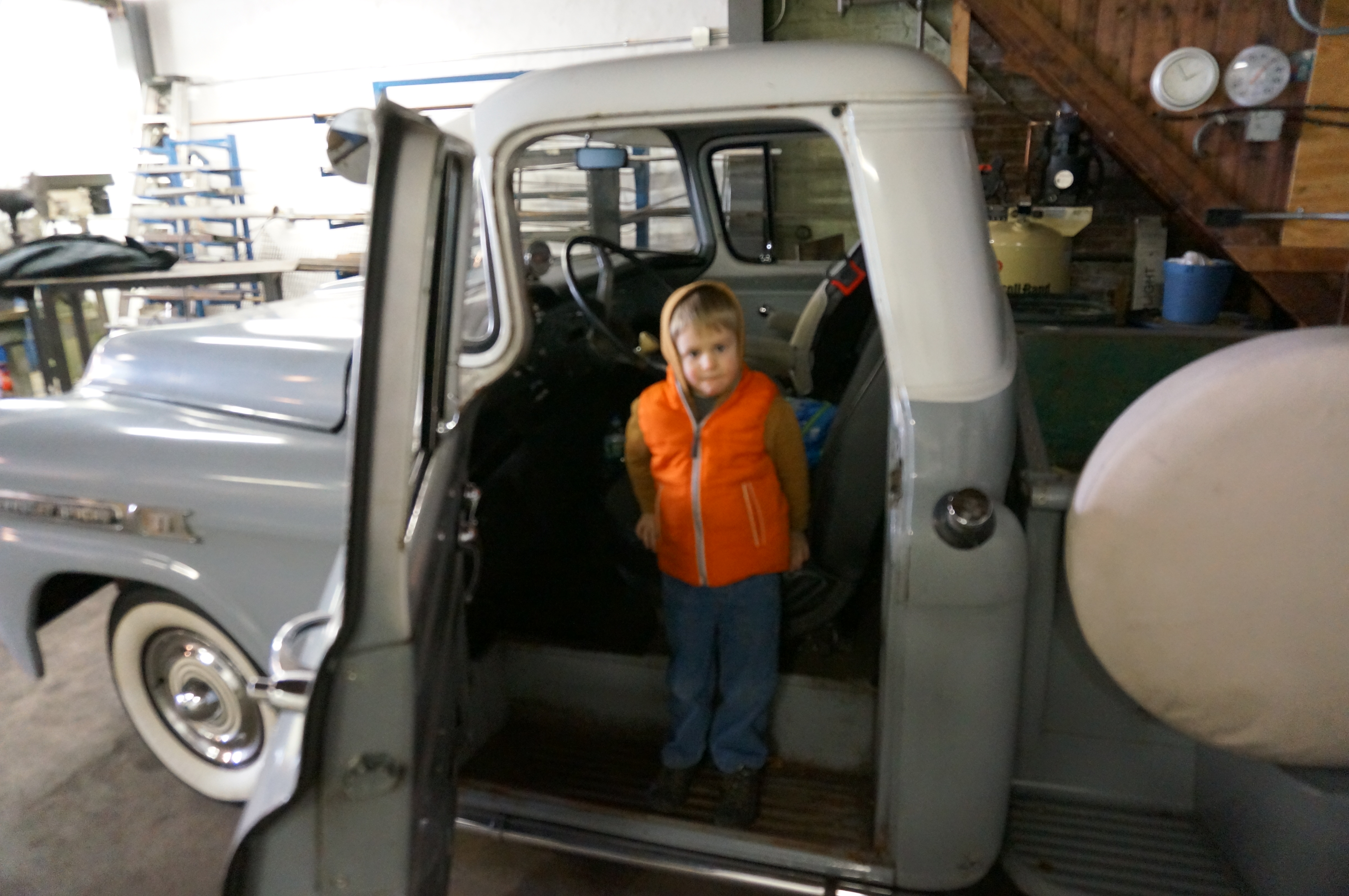
I’ve been fighting COVID-19 lock down boredom by keeping busy with a constant diet of projecs in my garage and around the house. It’s been six years since I created an article here, but boredom is the enemy so here goes . . .

A lot has changed since my last transmission:

  • I moved away from Philadelphia with my family to take a job in California.
  • I moth-balled my workshop (the one you see in all previous articles here) and took what could be shipped with me when I moved. The heavy machinery still lives in Philadelphia.
  • As my sons grow and learn (they are 6 and 9 currently) I try to teach them the project mindset with everything we do. Guess this is NOT a change since last time ;-0
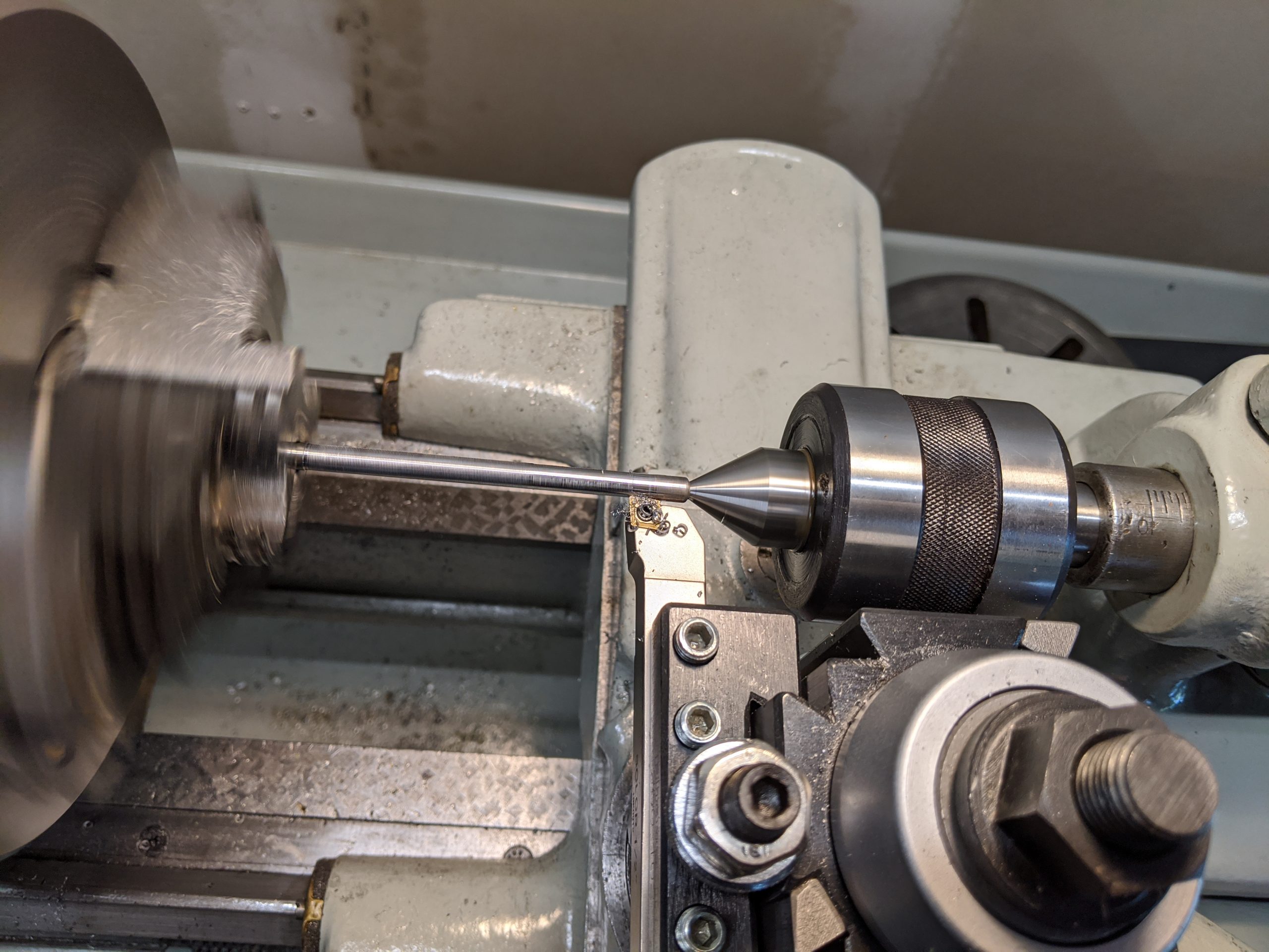
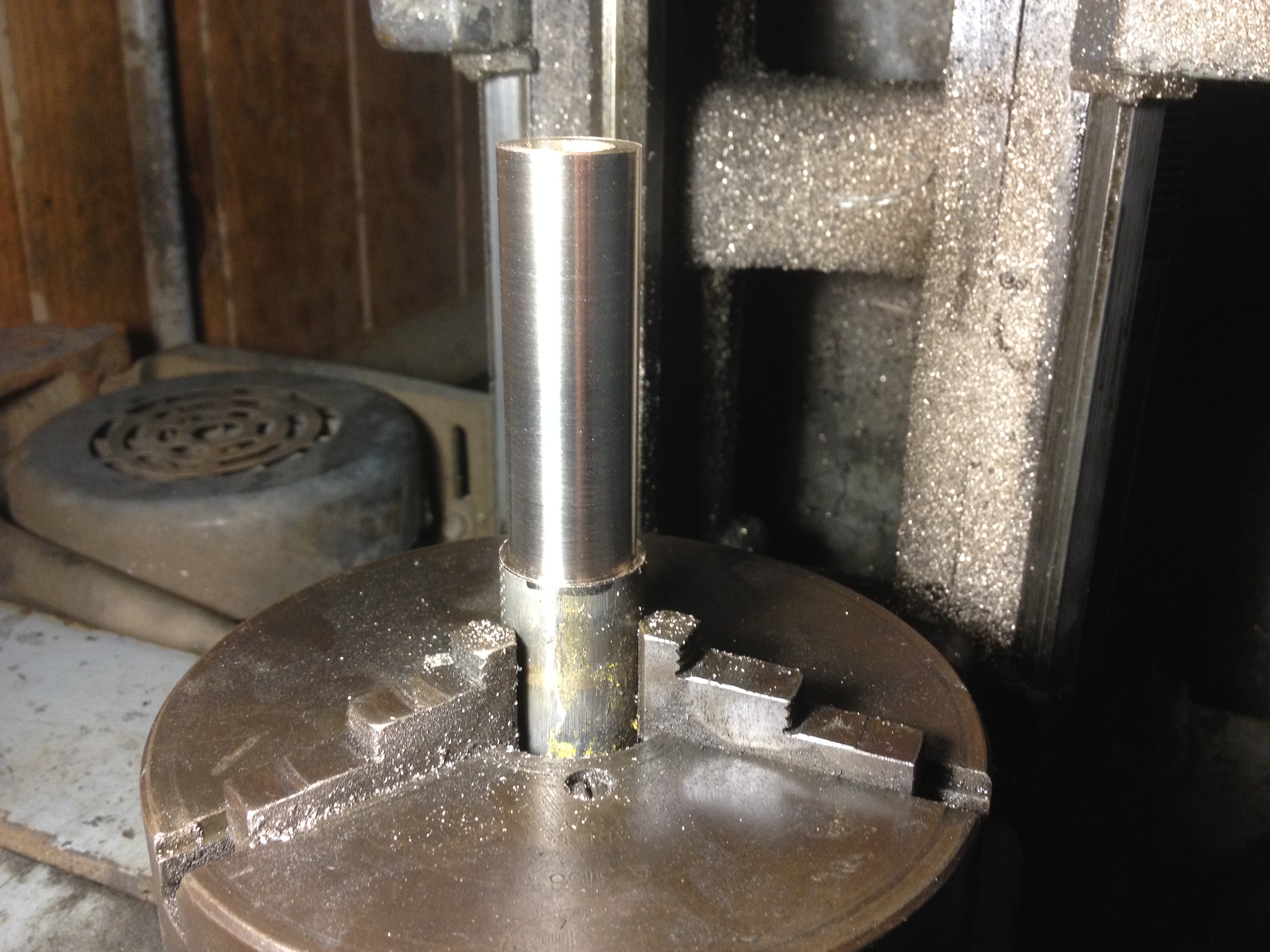
  • All projects are now down in my small-by-comparison two car garage. I’ve gotten back to basics and am enjoying it. I’m also employing some of my old methods of getting things done without all the fancy machining tools although I do still have a lathe.

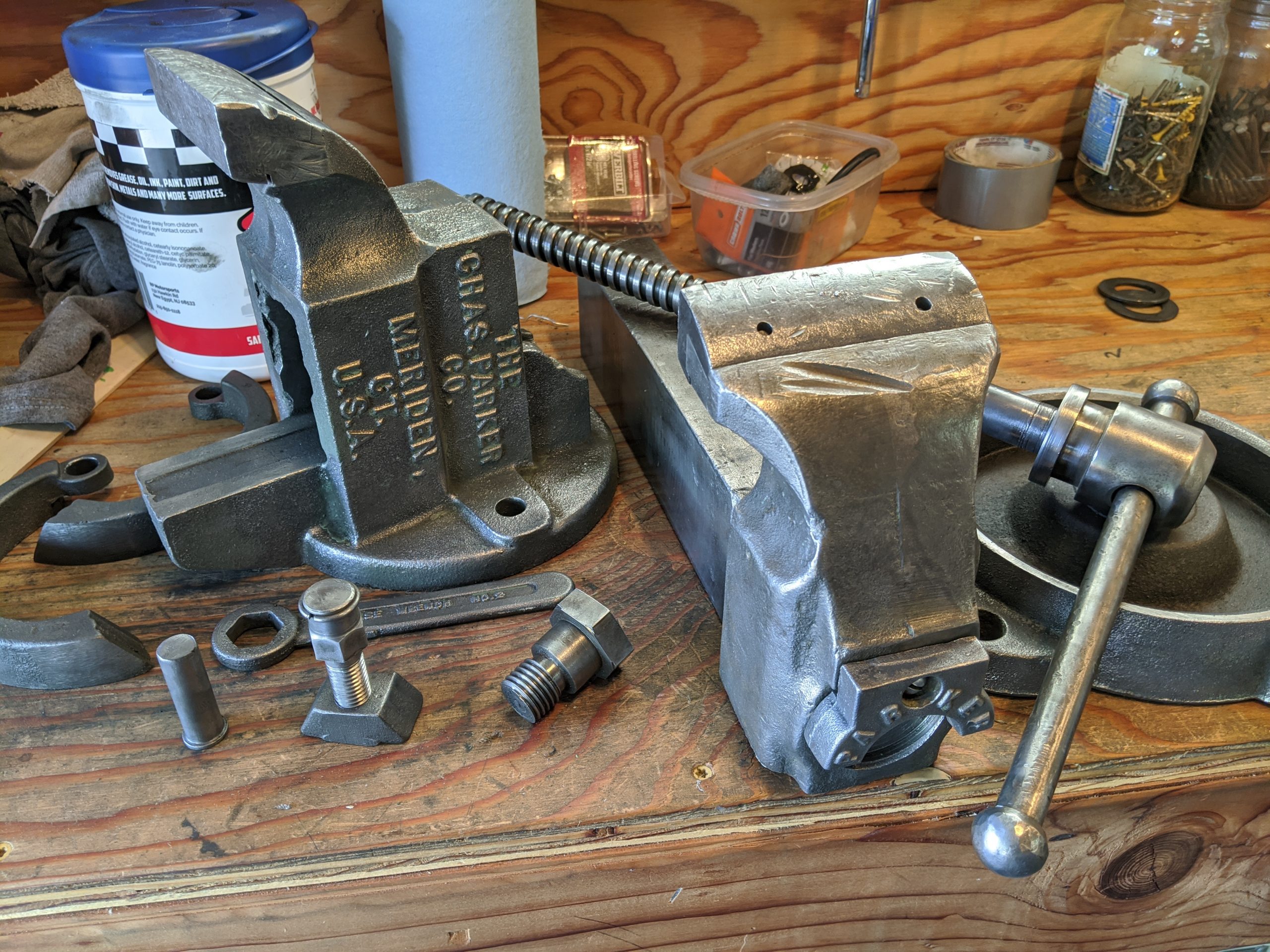
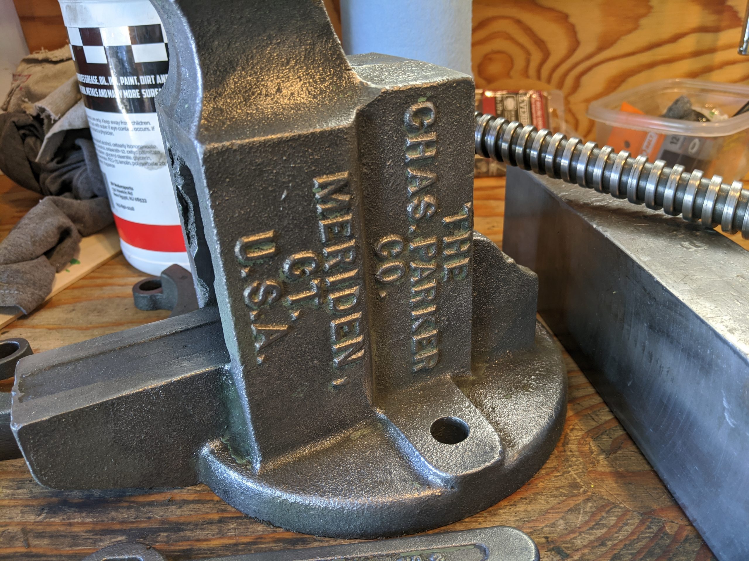
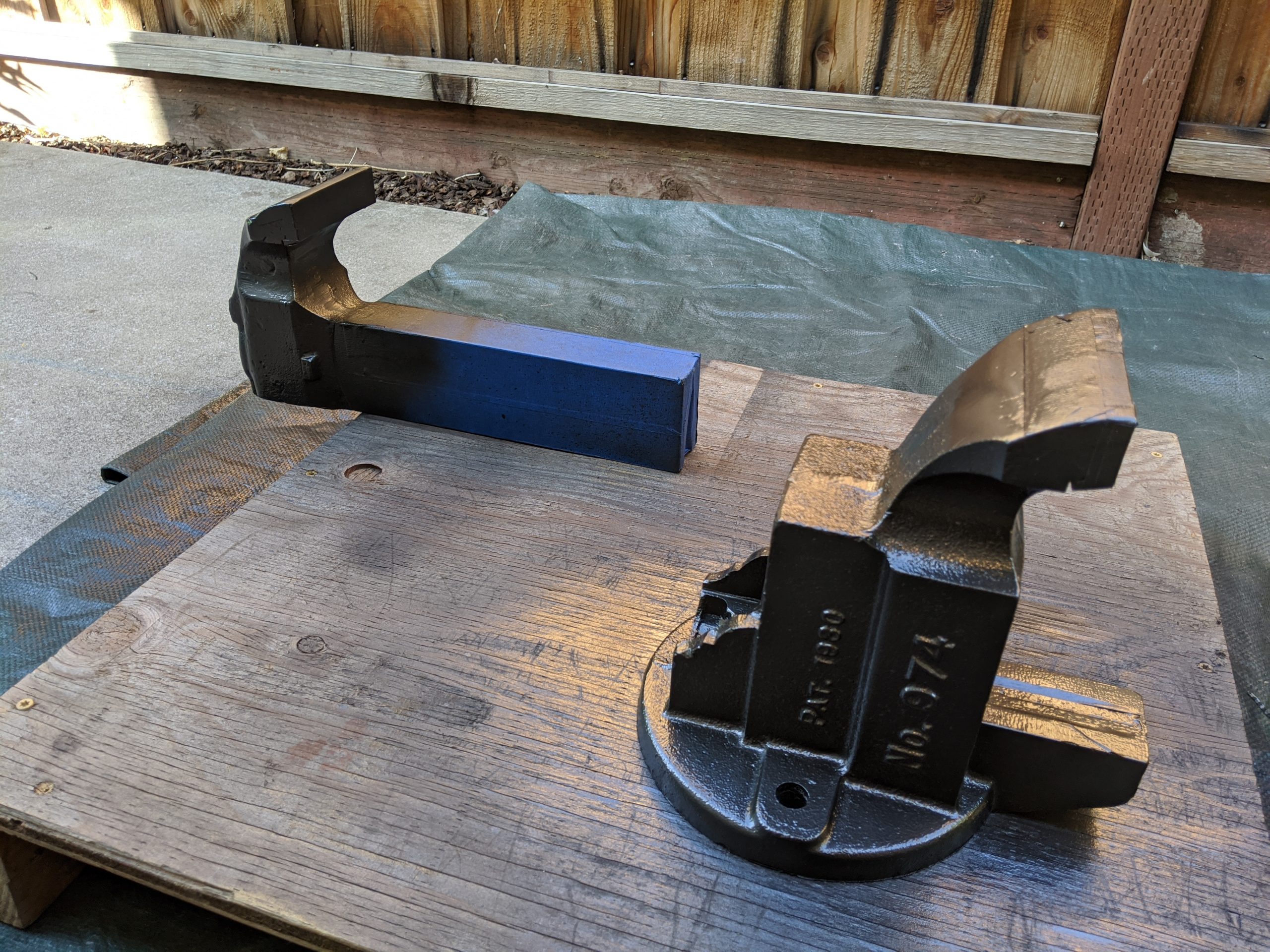
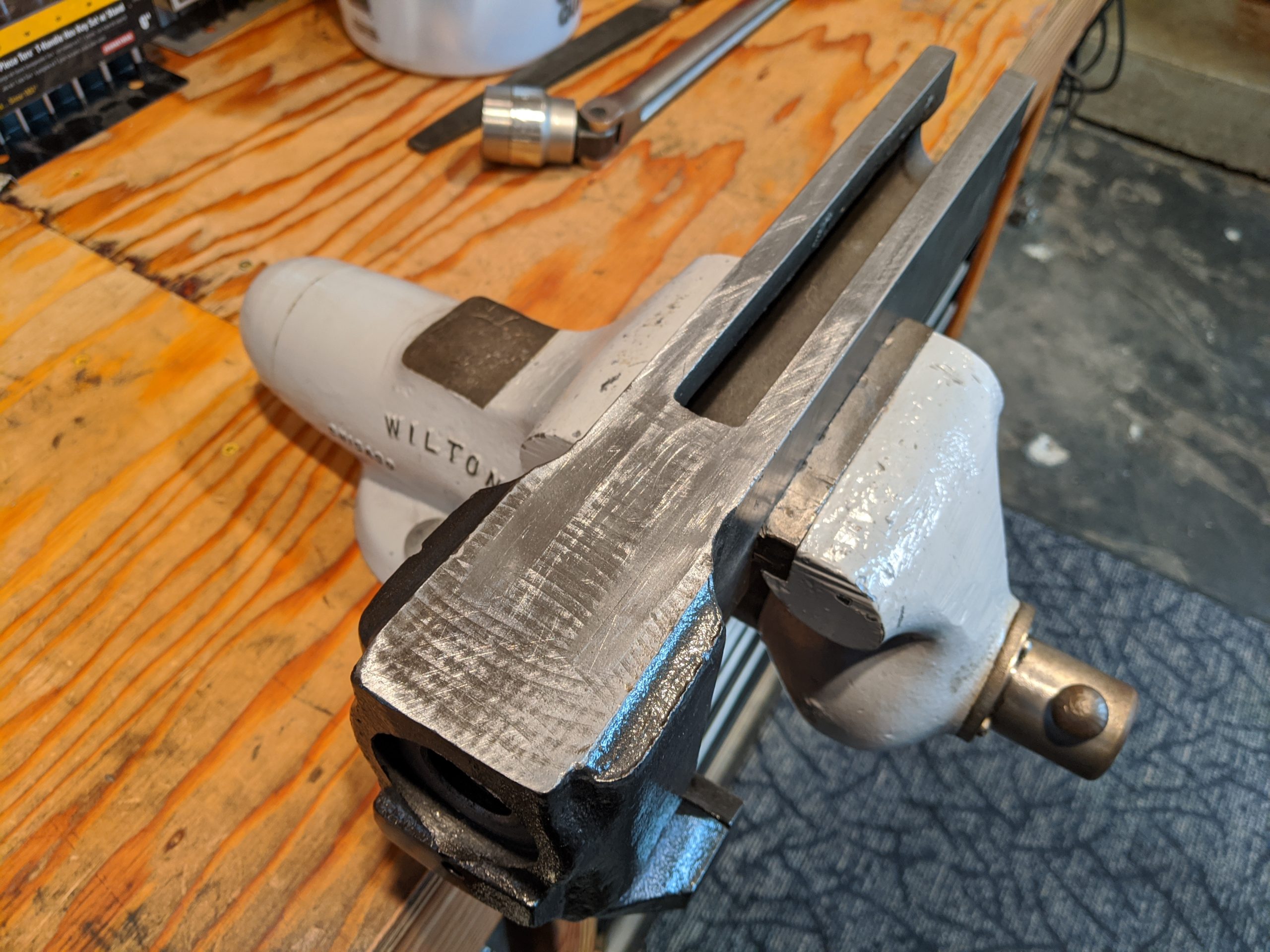
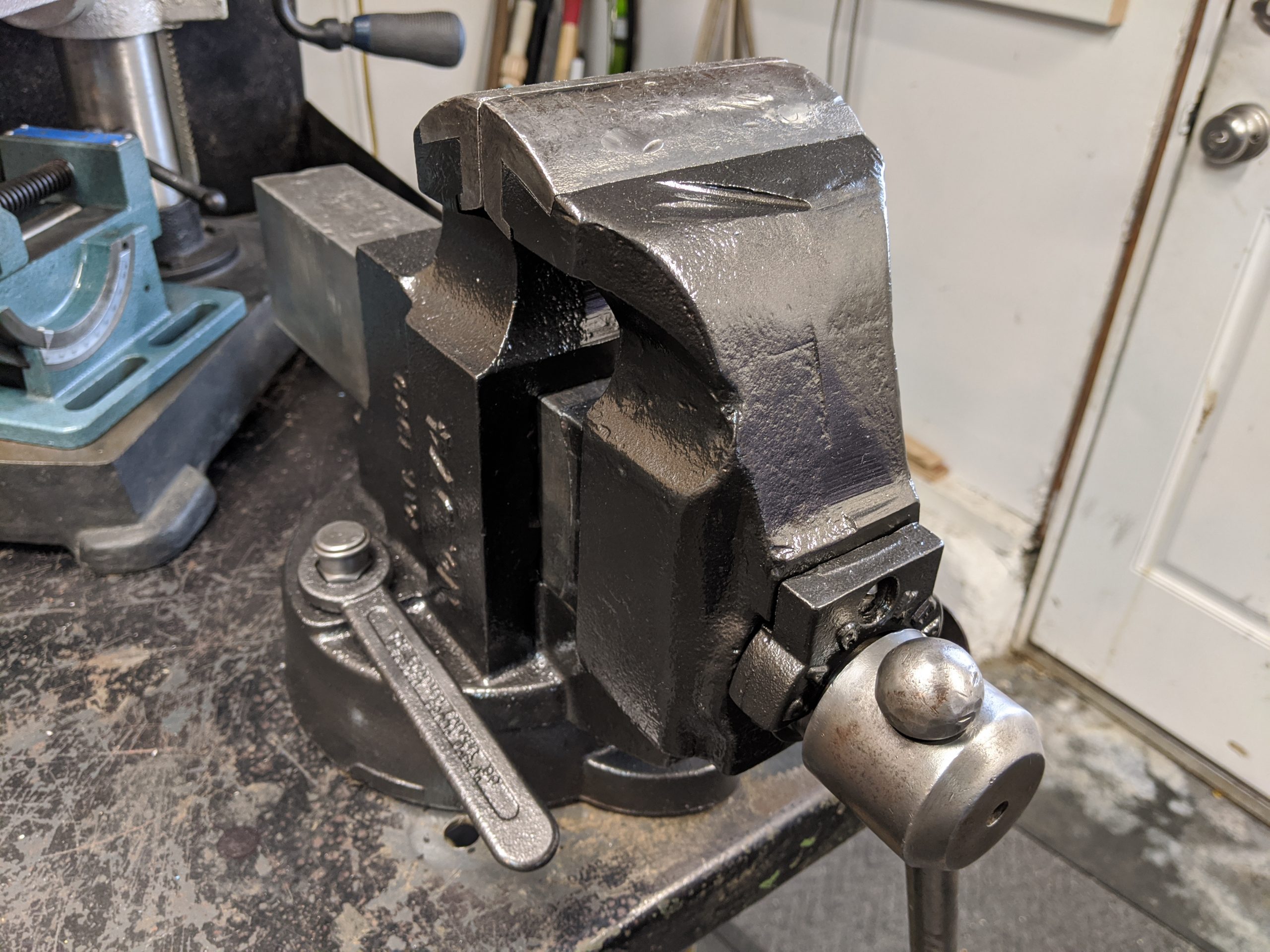
The house I was renting when we first moved here had an old garage with a hand-built workbench and a nice old vise. I used it for three years and became attached to using it. I asked the landlord if they’d sell it when we moved (after buying a house two doors away) but they told me it was their grandfather’s and had sentimental value. I can certainly appreciate that. So I have been looking out for listings off and on for the last few years for a Parker 974 just like that one.

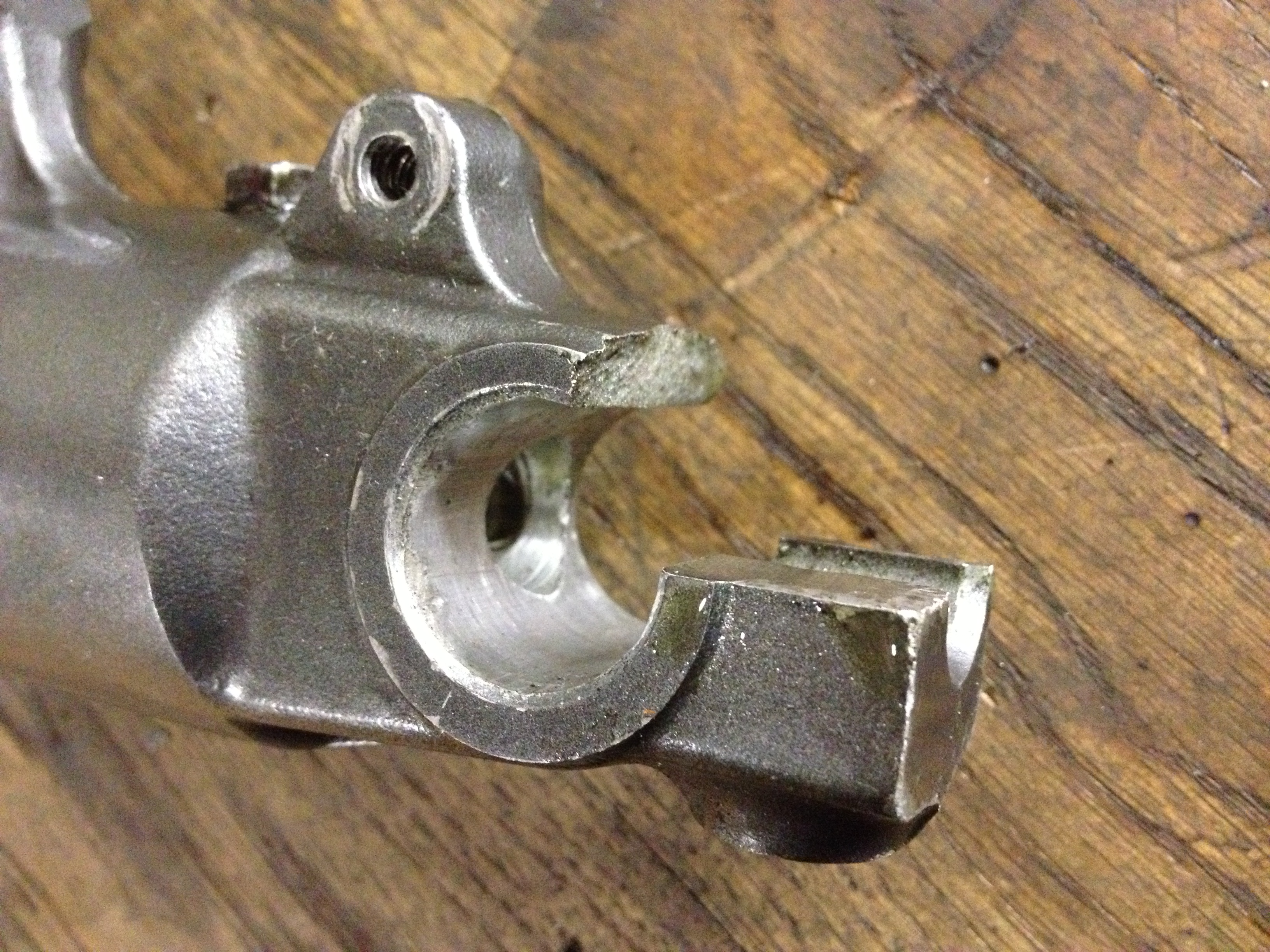
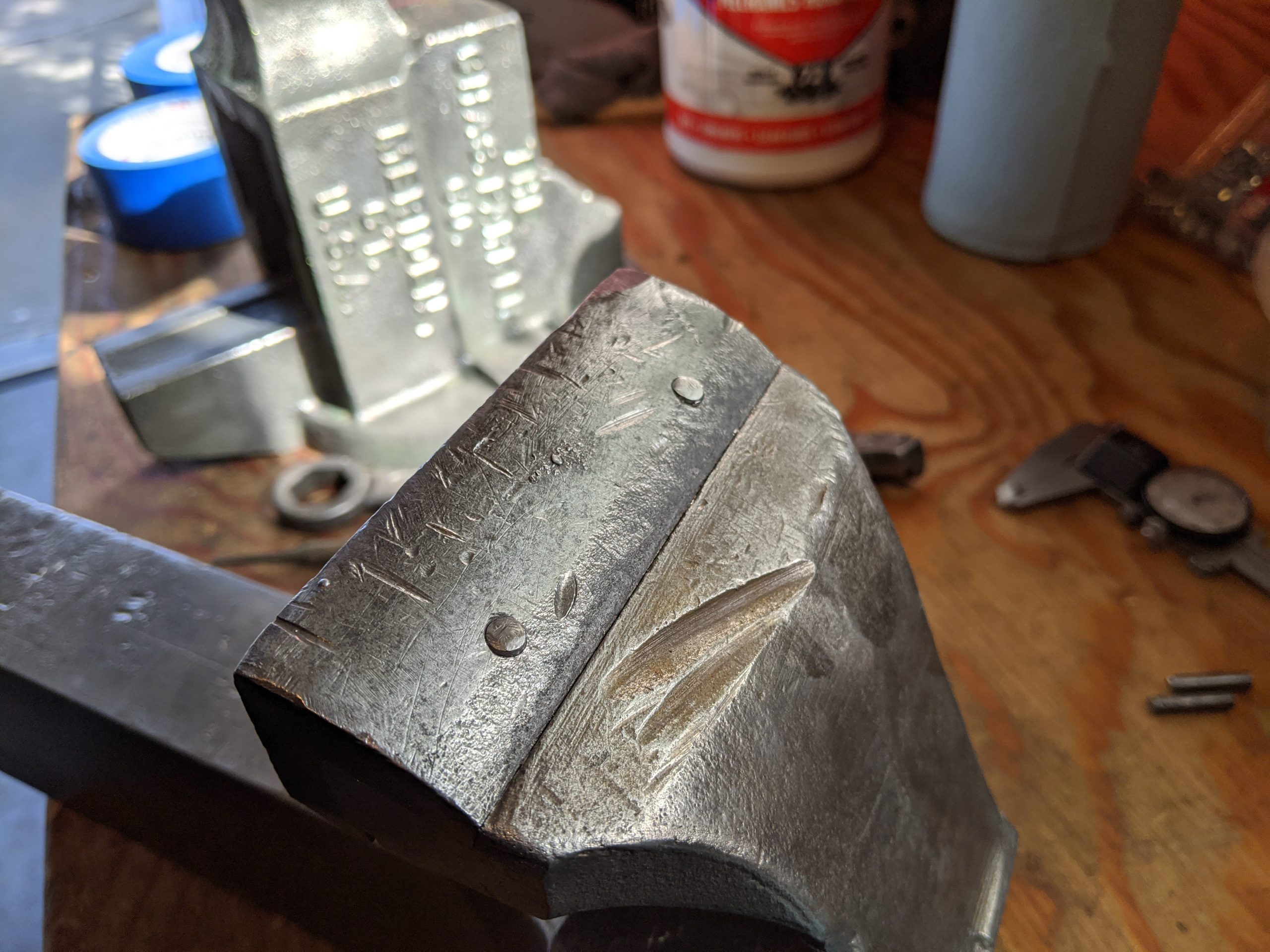
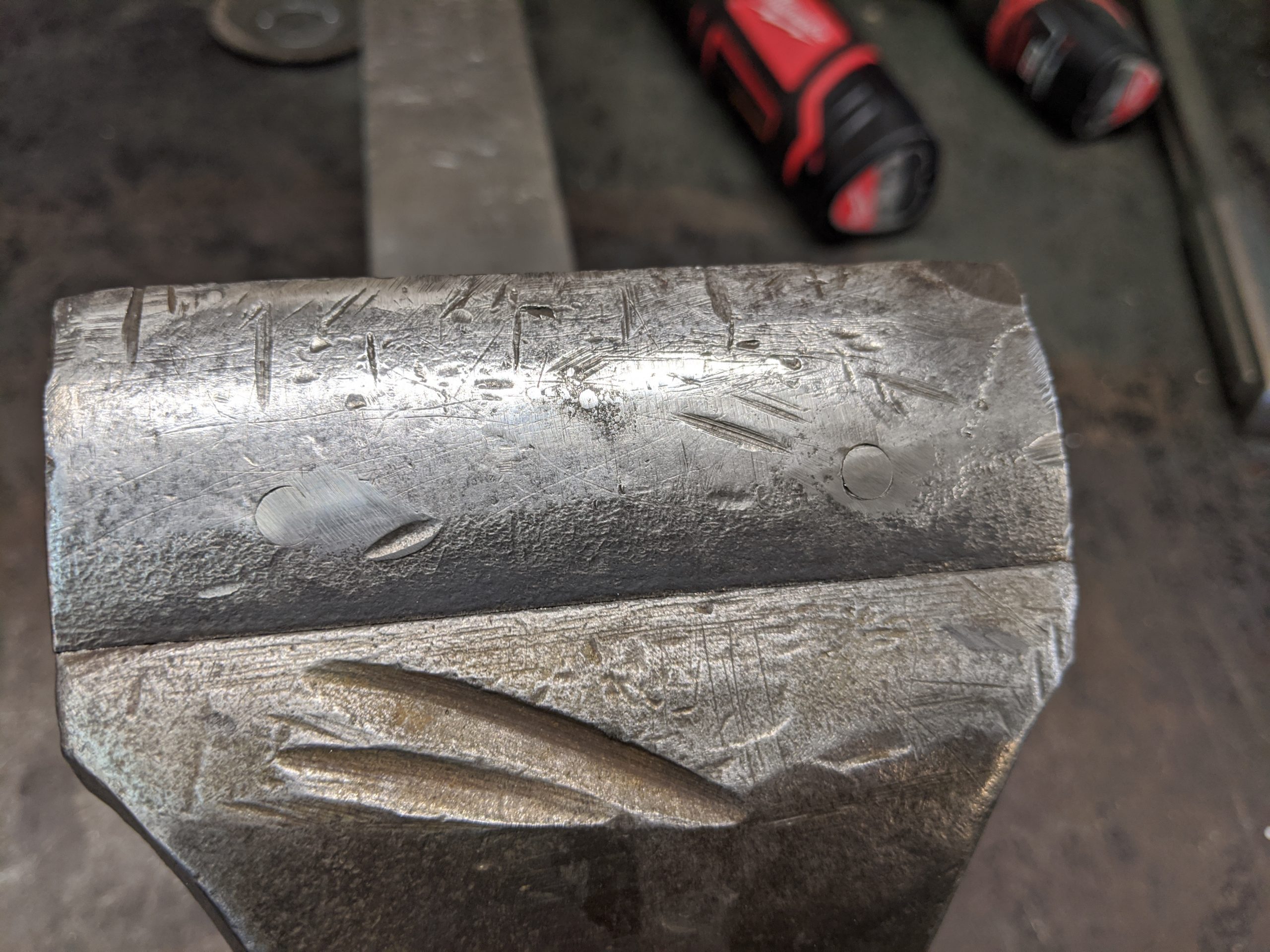
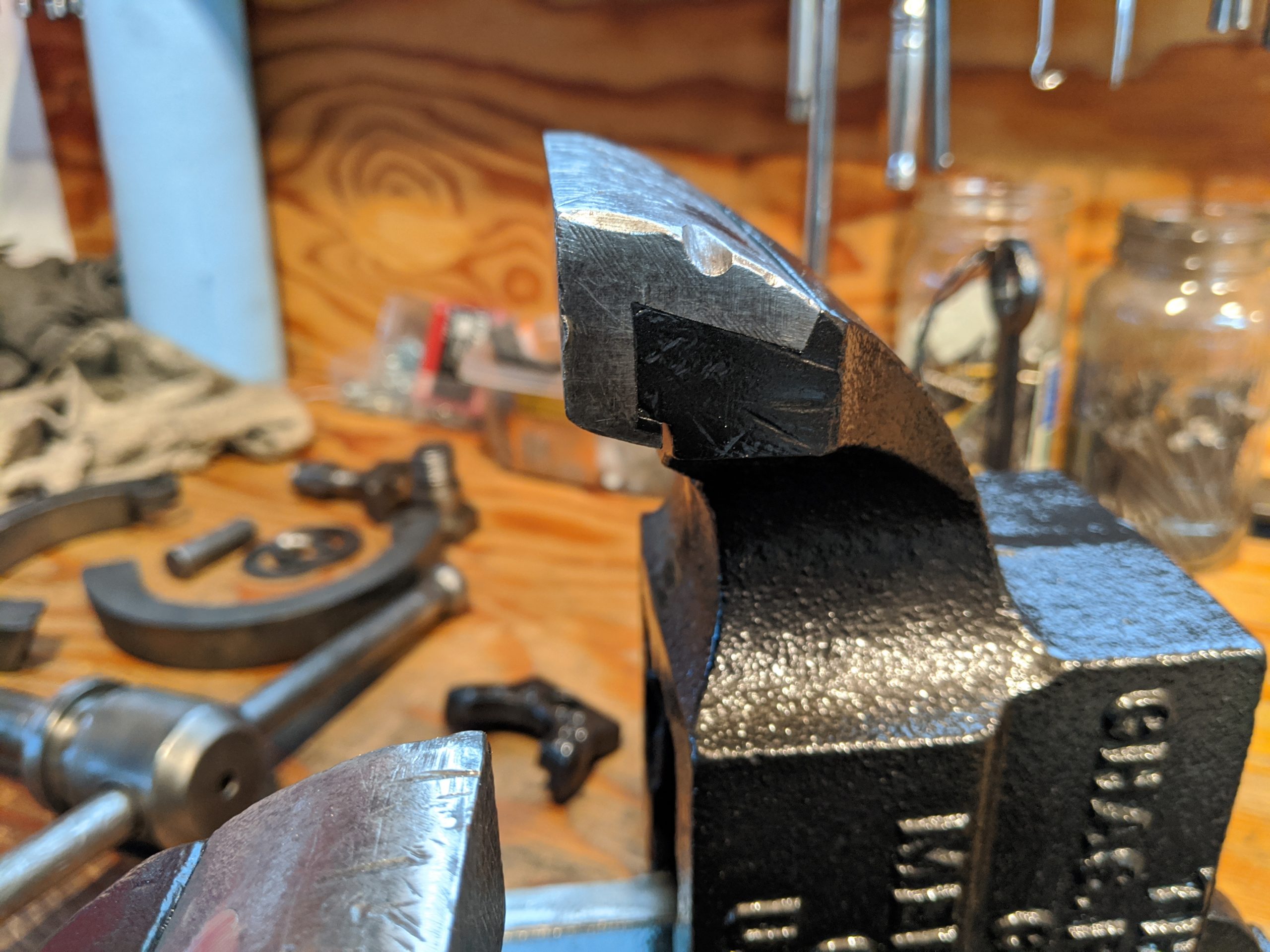
Two weeks ago I found one at a decent price with reasonable shipping charges, free in this case. Weighing around 80lbs, shipping cost is a big consideration. This one comes from Connecticut and has definitely seen some hard use but nothing is broken. My intent is to actually use it (more hard use!) so this suits me fine.

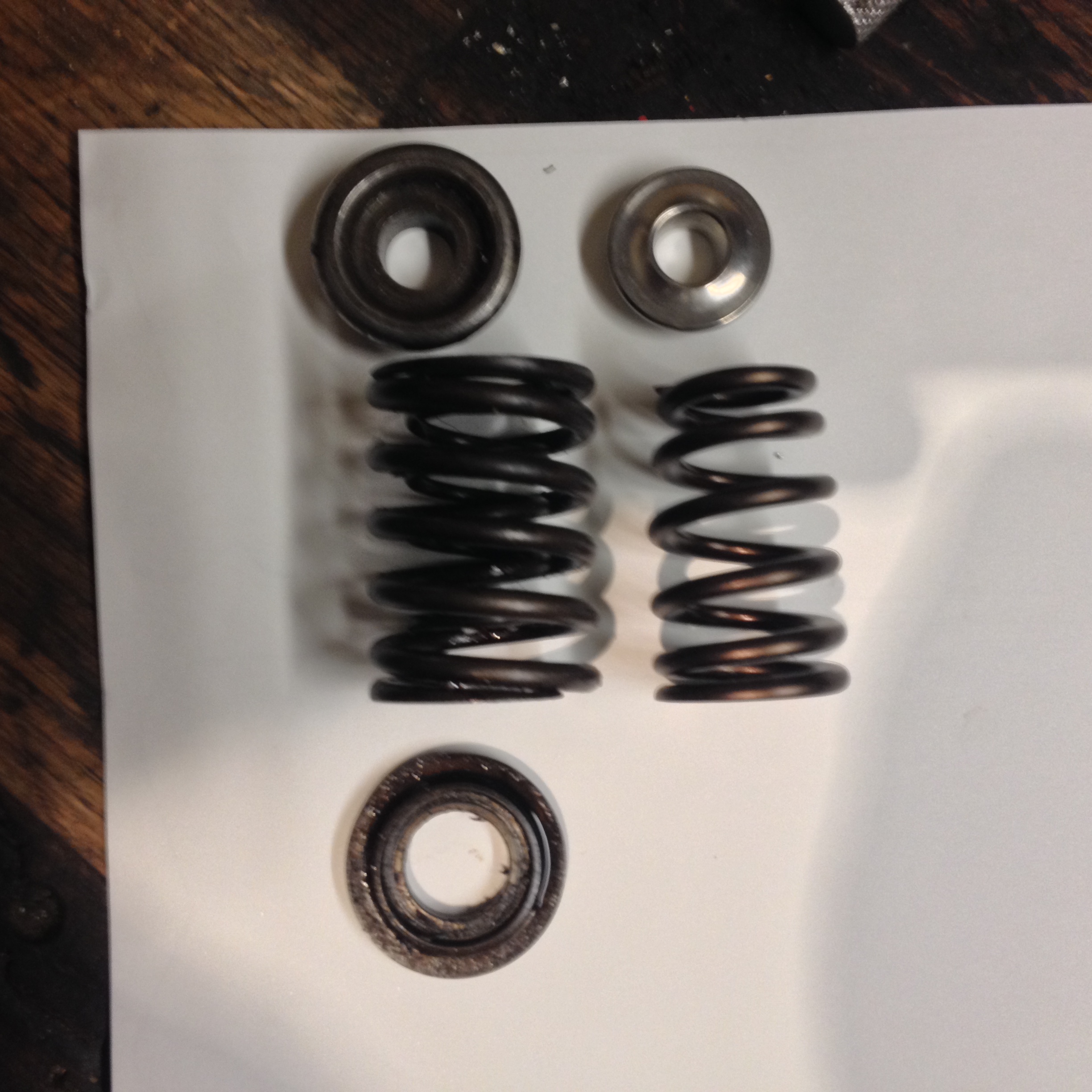
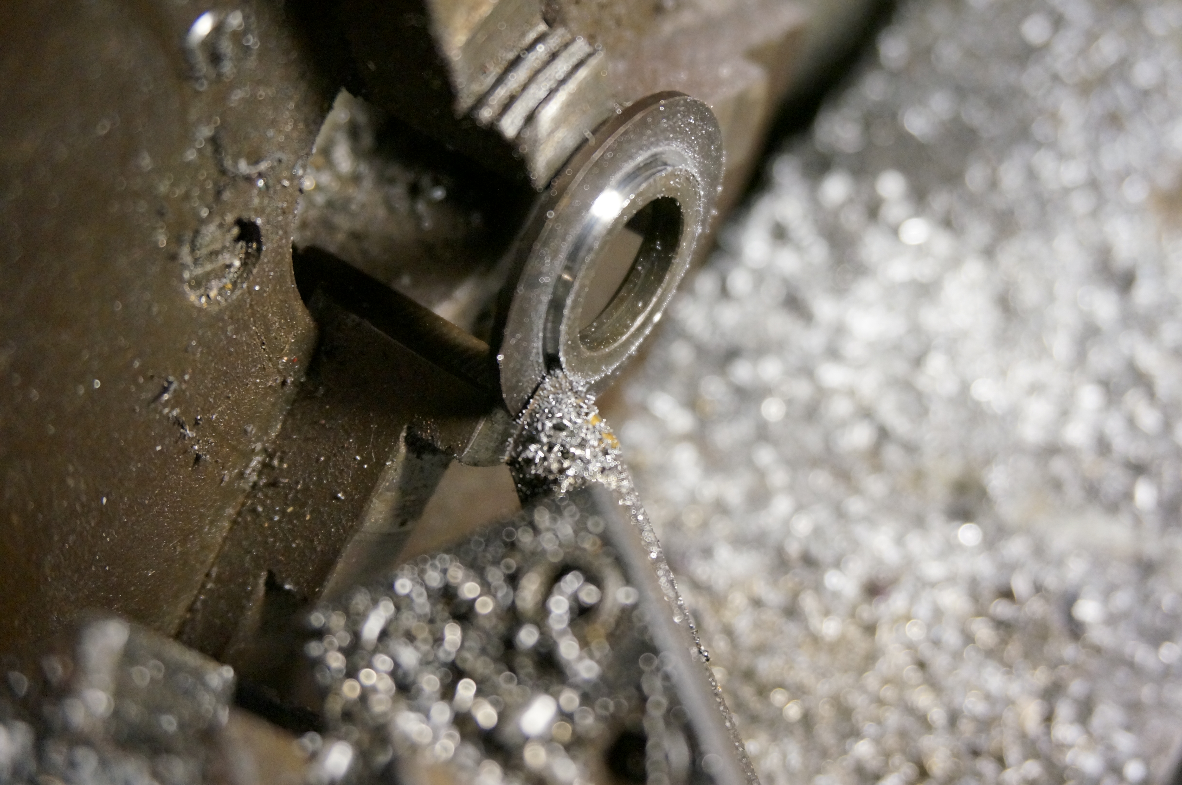
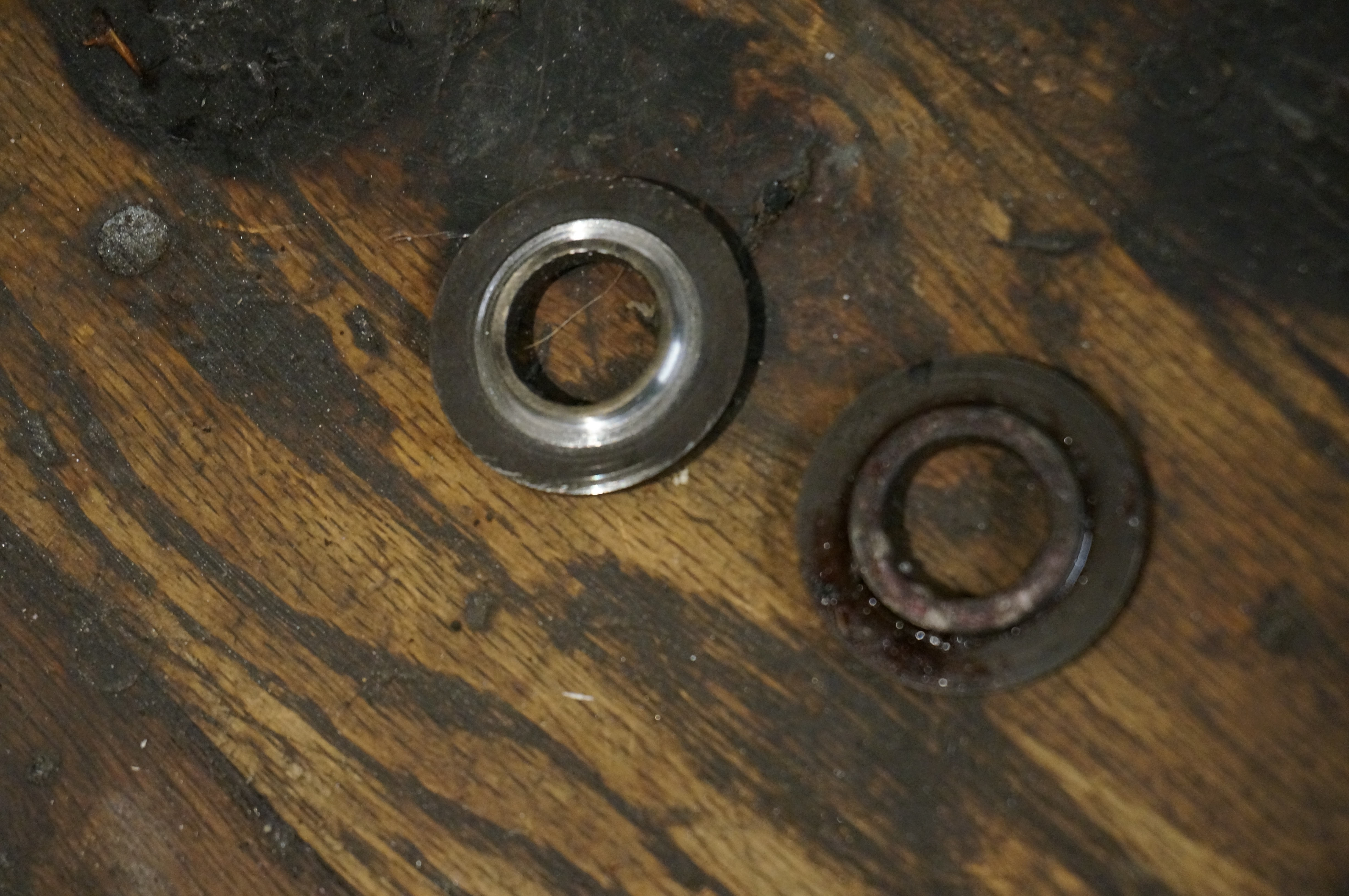
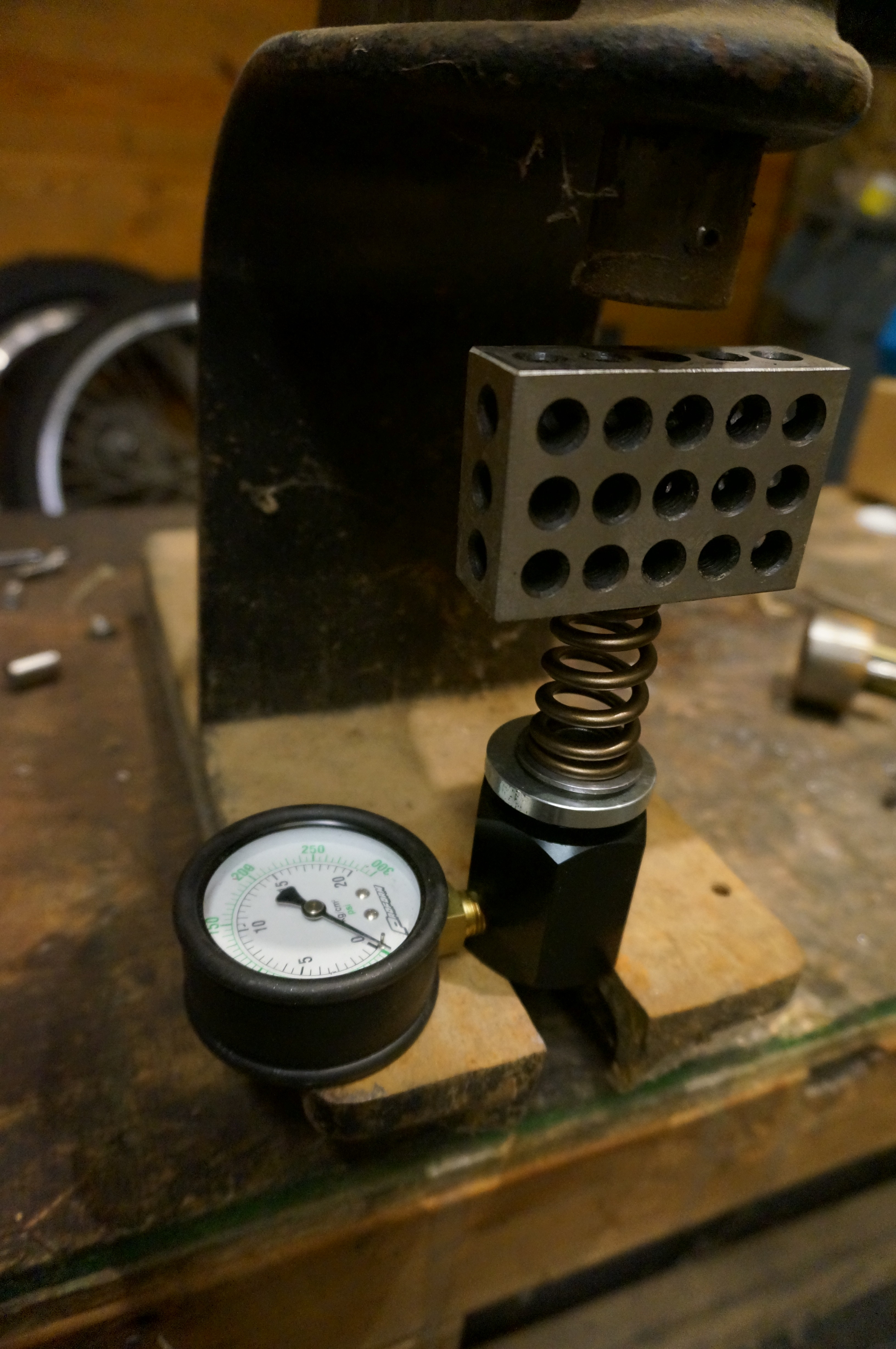
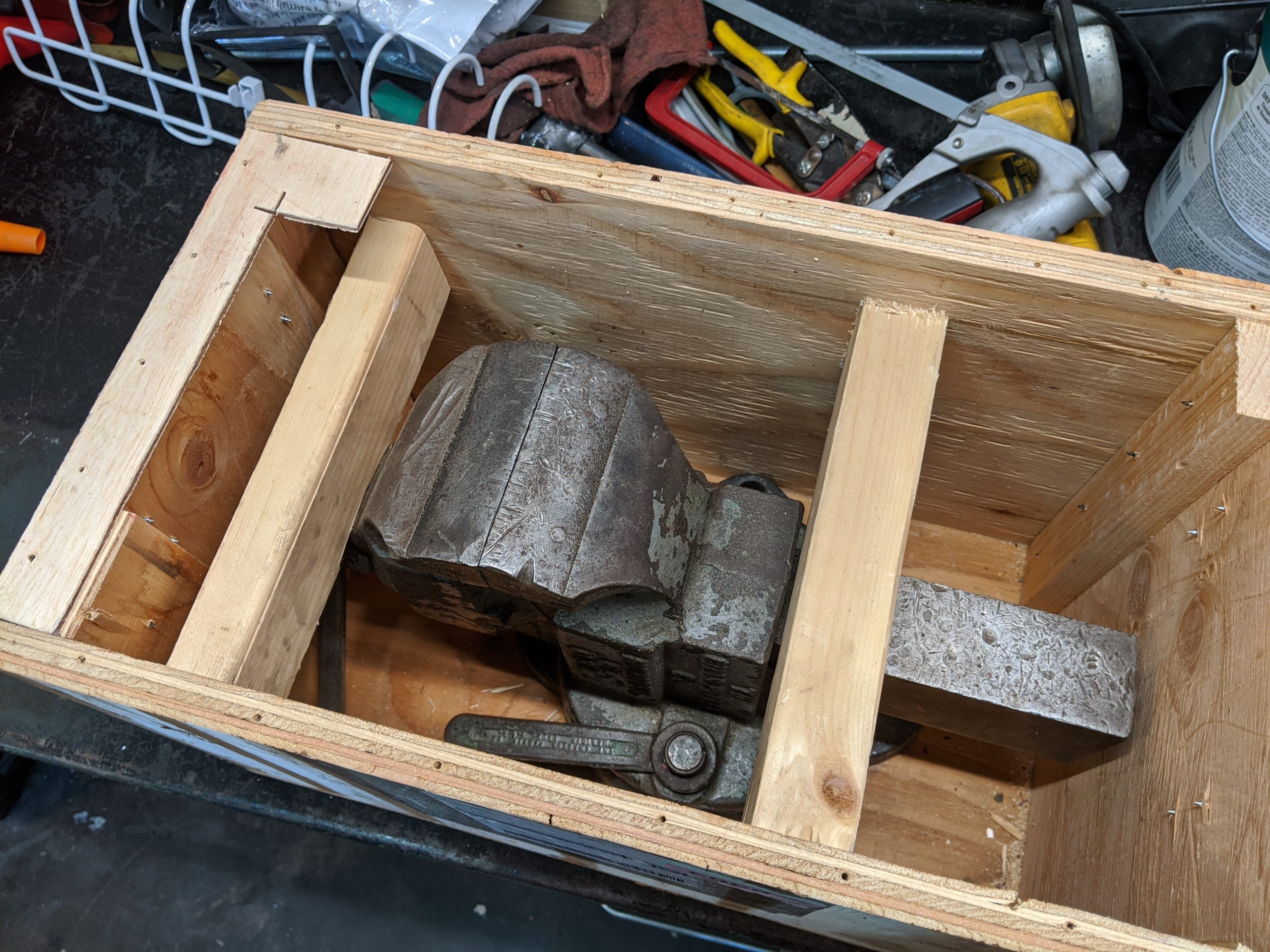
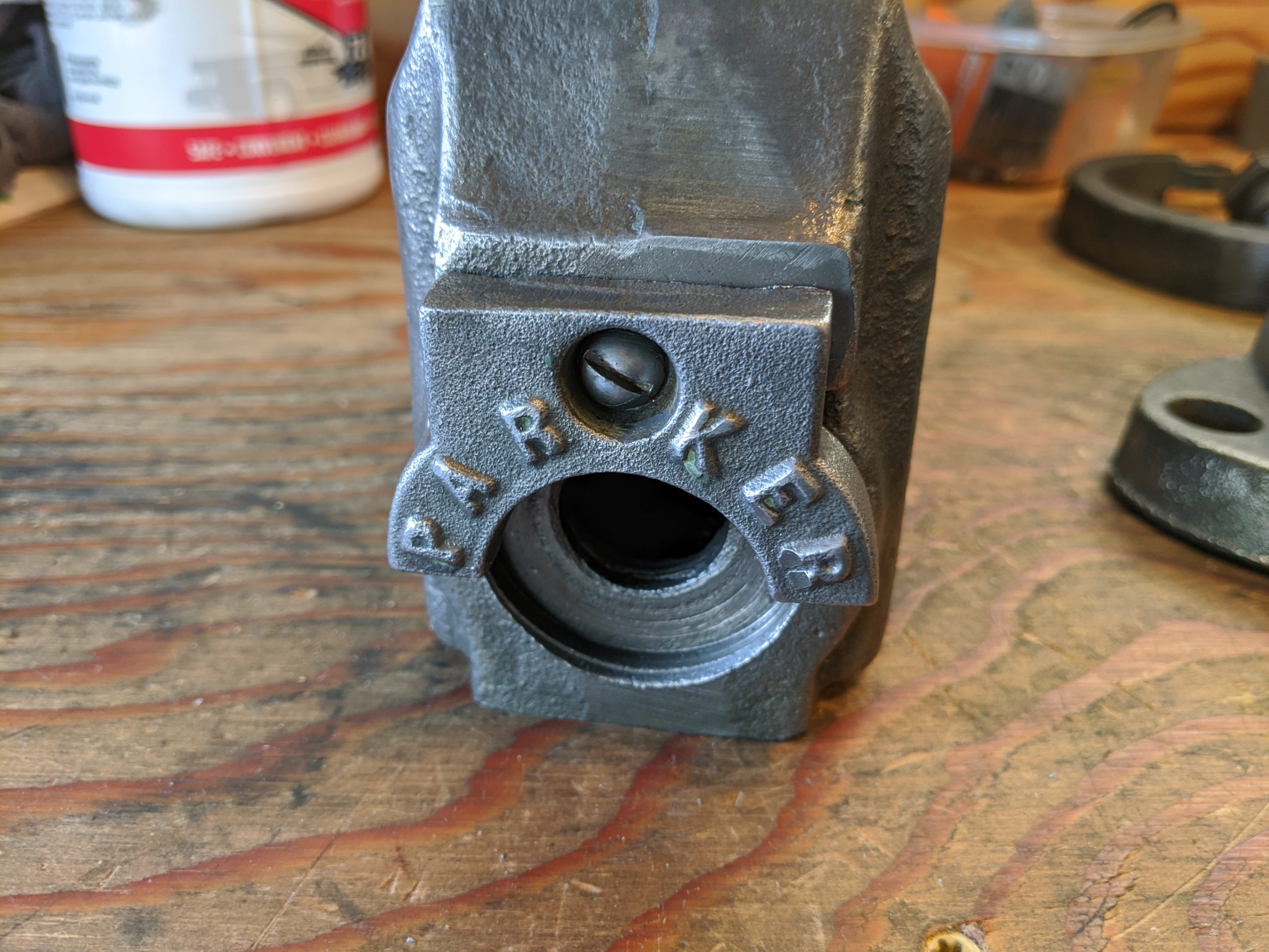
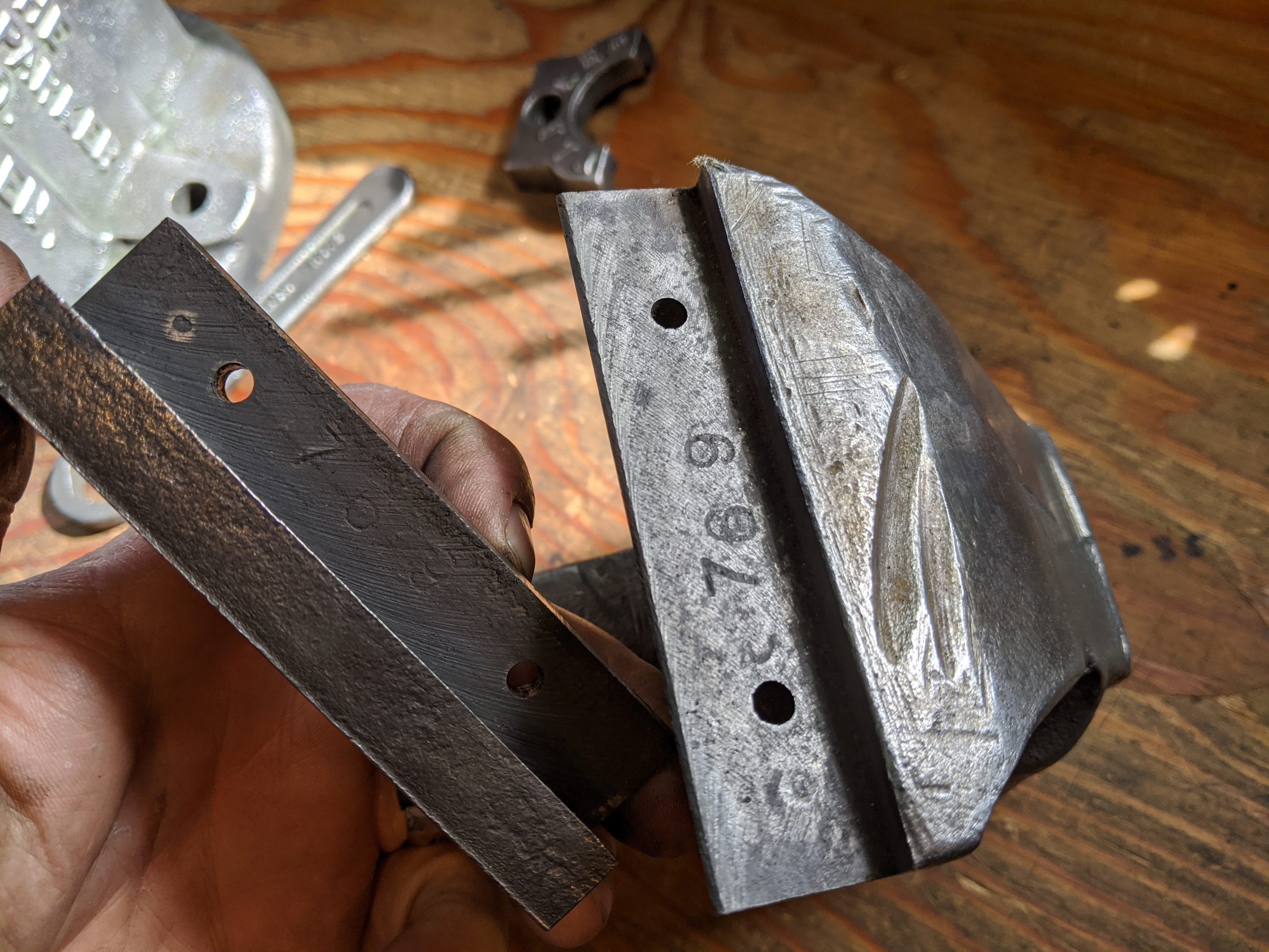
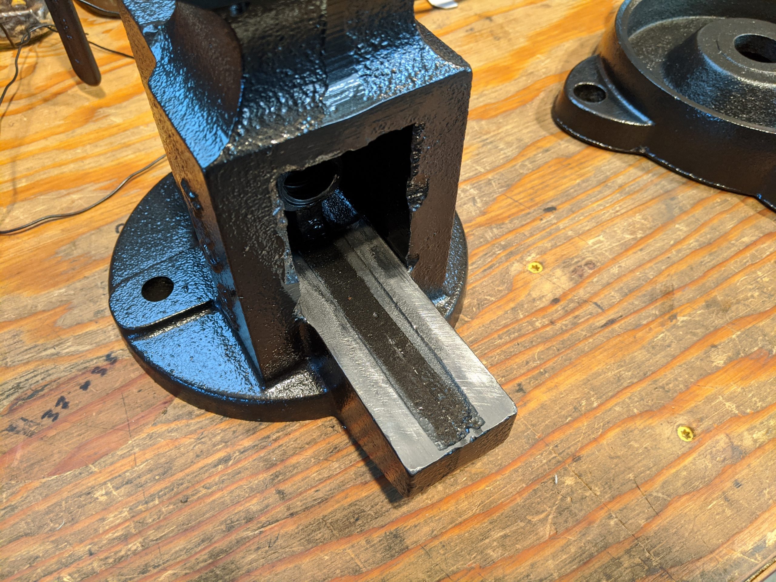
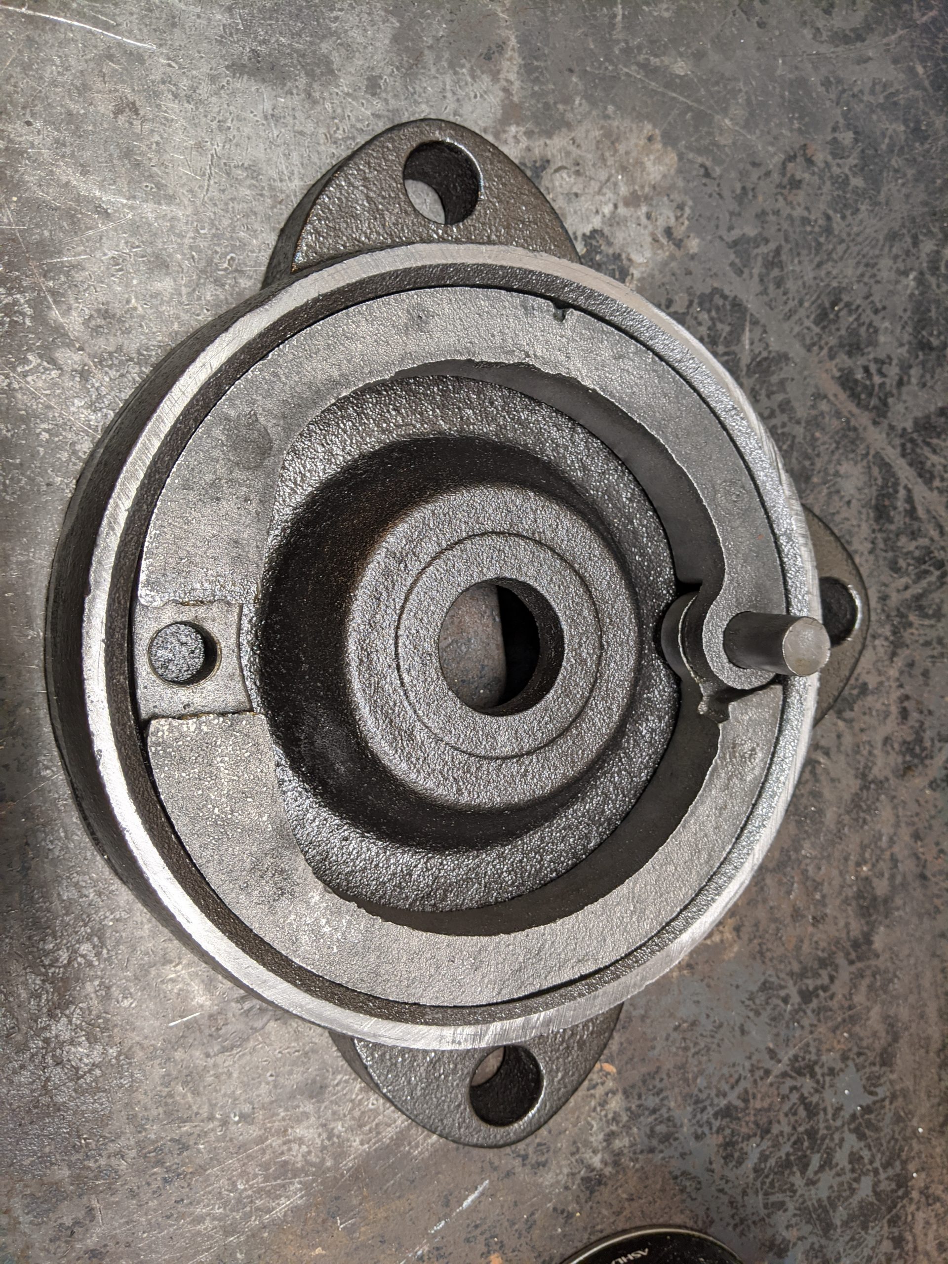
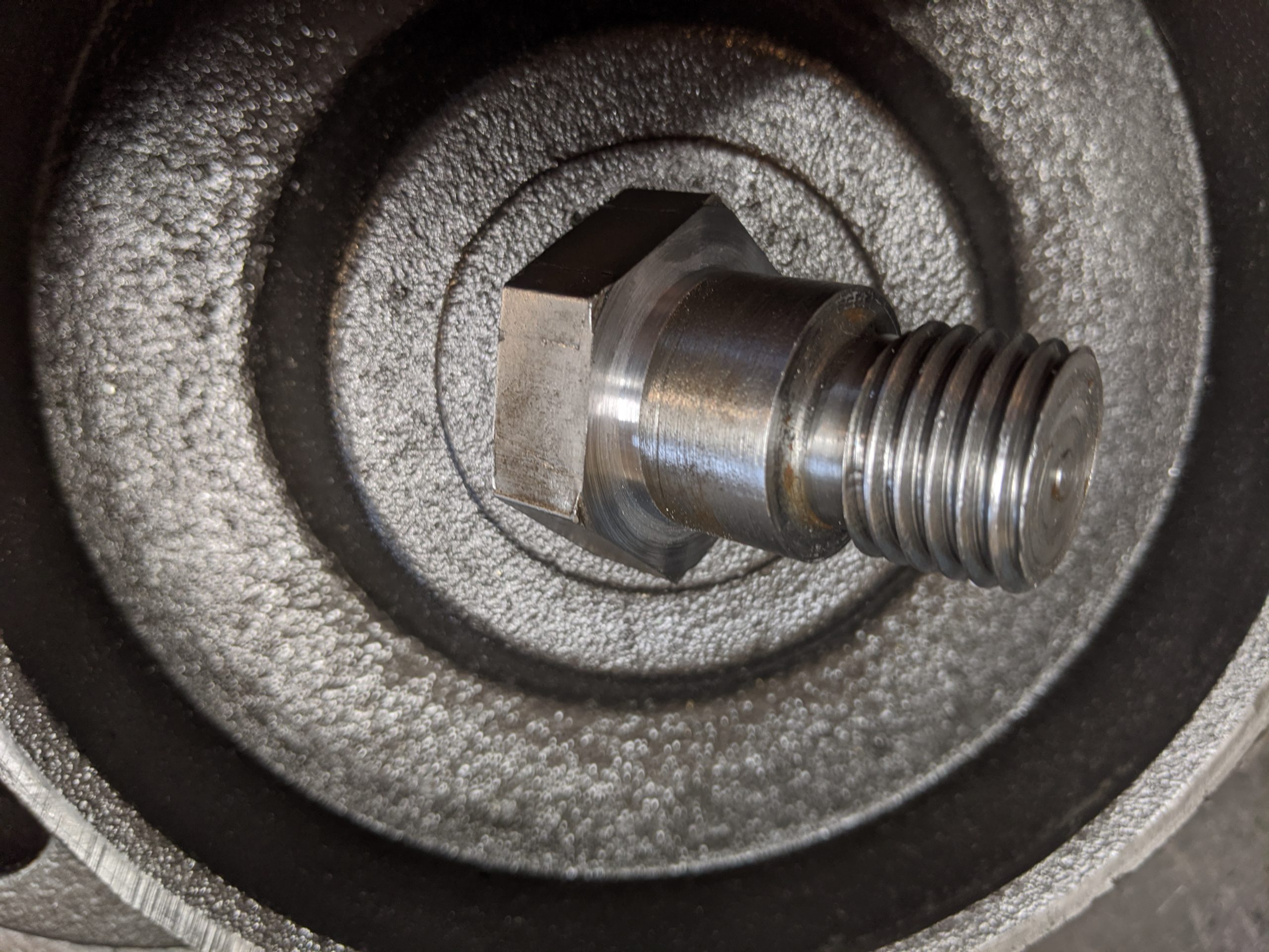
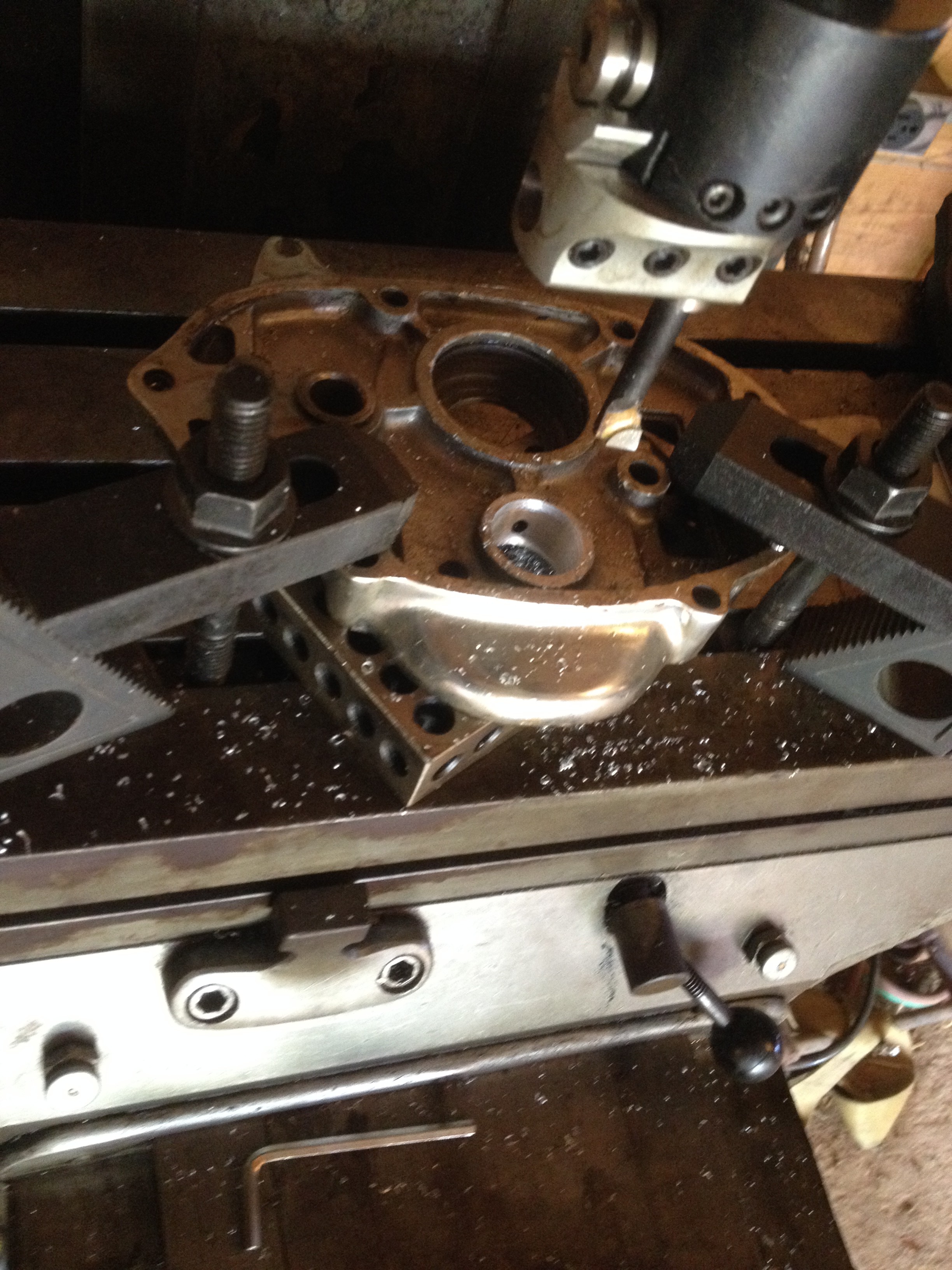
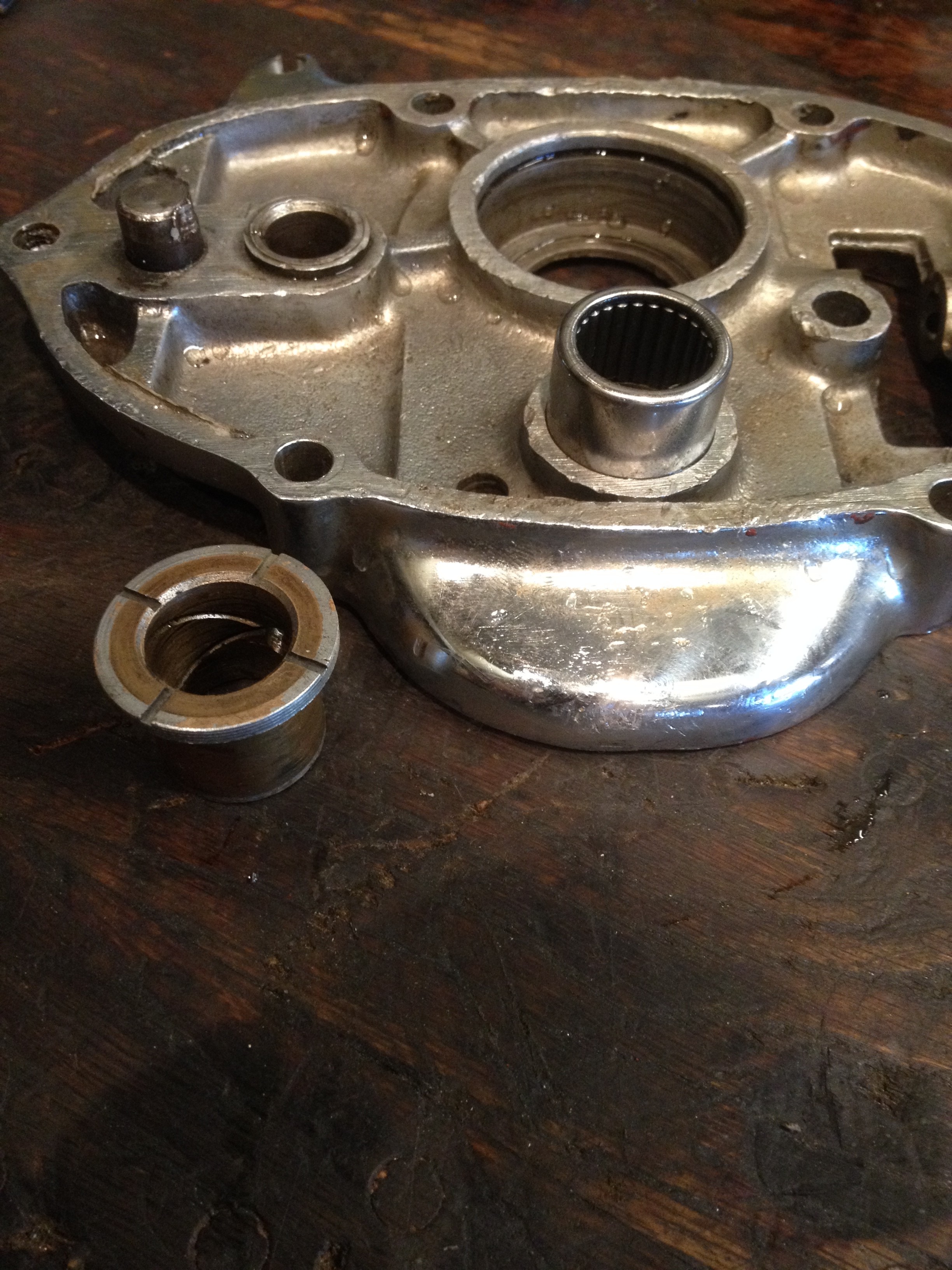
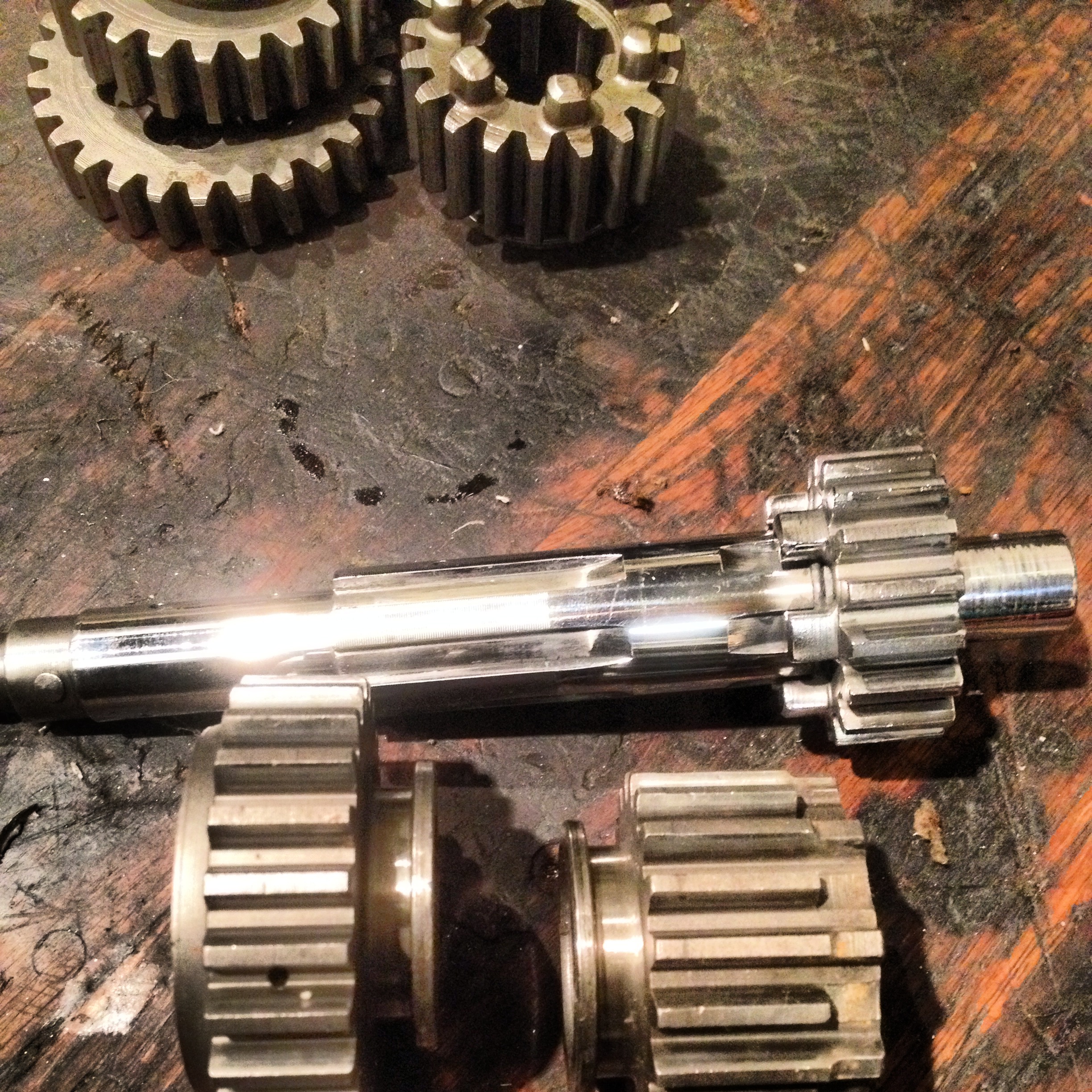
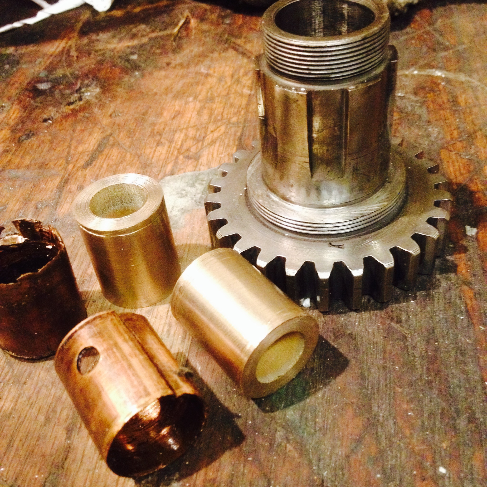
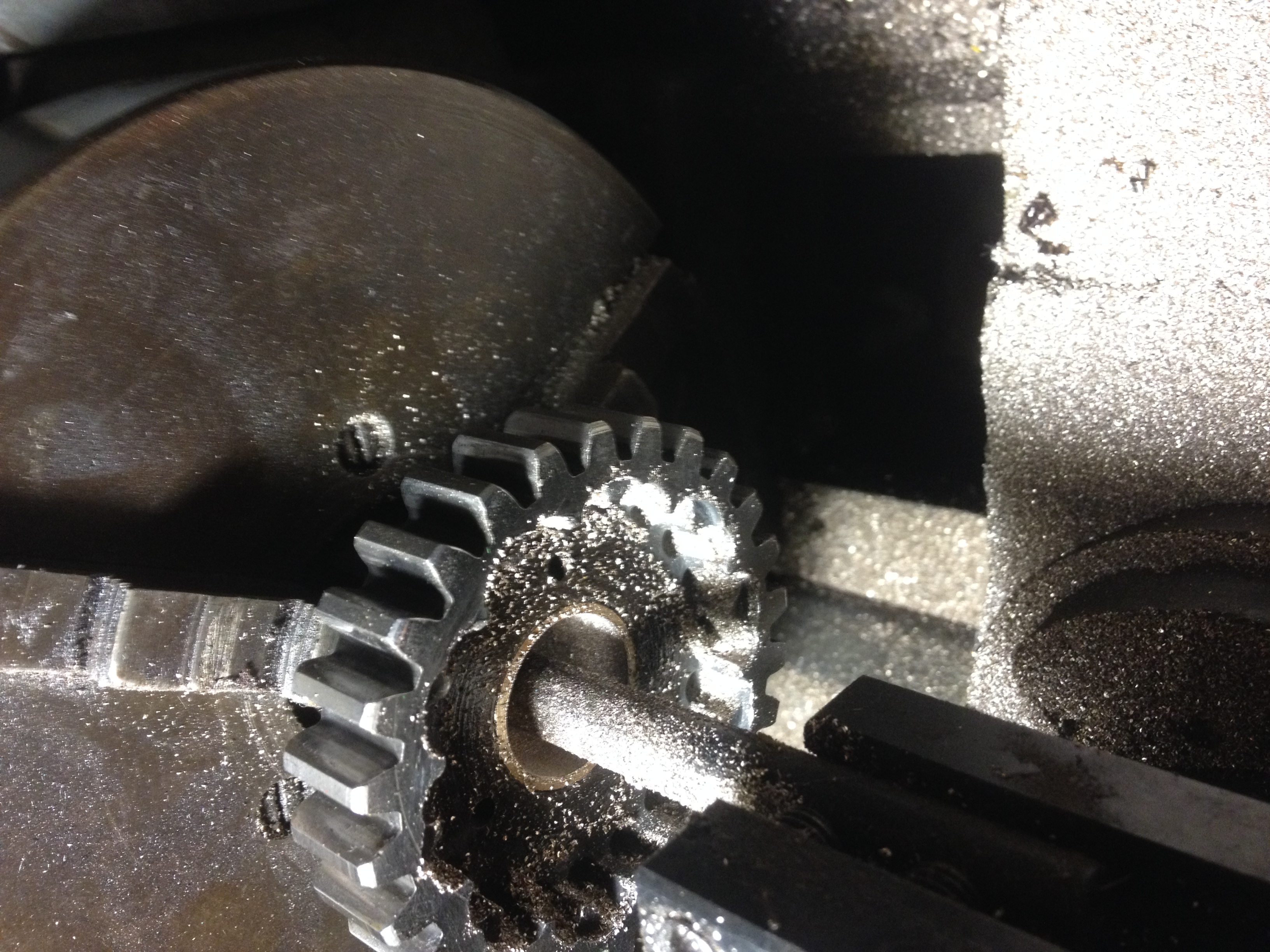
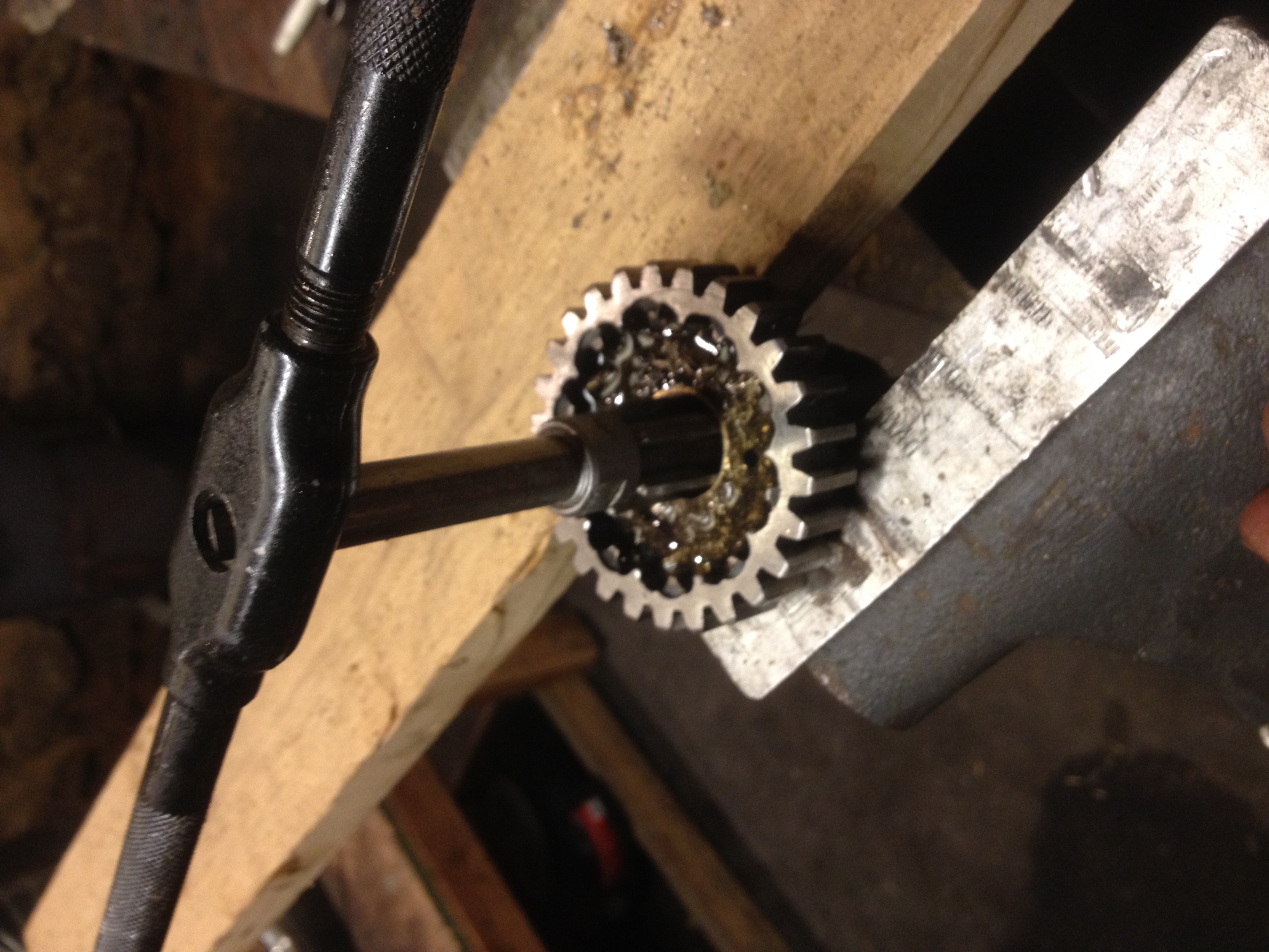
When it got here I was impressed by the care the shipper took in crating it. That’s always a good sign. I was going to just bolt it down and use it but then spontaneously disassembled it and starting cleaning it up and looking for any needed repairs. The rest of this article tells the tale.

Nice to be back.

Jason (May 2020)

(click on pics to see full size)

click on image for full-size view
This is how the vise arrived. Well made crate with the vise secured inside. I half expected it to arrive packed loosely in a huge wood box . . . and bent or broken.
click on image for full size view
Within an hour of having received it, I had it complete disassembled. I used a wire wheel to strip three layers of paint away. Was originally black, then someone painted it mint green, then someone painted it machine grey.
Main vise body/receiver after stripping and inspection. No cracks. All good. This is a stout casting.
The slide jaw retainer (connects the main screw to the sliding jaw for opening the vise) had a large gap where it meets the jaw. Didn’t matter for 80 years but I ground it down for a better fit anyway. I’ve got the time.
Sliding jaw retainer after stripping and repair for better fit.

The hardened steel replaceable jaw was loose when I got it. They are pretty tough to find once broken so I decided to fix it. The holes are for press-fit steel pins used to secure the jaw to the casting. I removed them with a drift pin and took a pic of the part numbers for future reference.
Making new slightly oversize pins to secure the jaws. The ones I removed were around .008″. I did not inspect the holes so I just made the new ones at .010″ to force them in place for a secure fit. Lathe is a 1944 South Bend 10L I recently put back into service.
Jaw reinstalled with the new oversize retainer pins. Pins were a nice tight fit requiring some force to install but not enough to risk cracking anything.
New jaw retainer pins cut off near flush for finishing.
Retainer pins ground flush with a flap wheel.
After carefully masking off the machined and sliding surfaces I took outside to paint. I used whatever hammered finish paint they had at the hardware store. I think the color was called “carbon”. Had the usual annoyances with the shitty can and nozzle design blowing spatters everywhere.
I cleaned up the sliding surfaces with a hand file and a whetstone. Didn’t go nuts on it, just made sure it was clean with no burrs.
I cleaned up the sliding surface of the moving jaw with a hand file and whetstone too.
Finished jaw repair after painting and removing masking tape.
You guessed it . . . more hand filing and whetstone. This time the sliding surface where main body/receiver rotates on the base casting. This vise has a cool lock design that allows it to rotate and lock in an infinite number of positions. The two things that look like old drum brake shows? They pretty much are. The set screw from the top pulls up the expander wedge locking the vise securely in place. The main body/receiver is also drilled symmetrically so you can mount the set screw on the right or left side. My bench as a side rail on the right so I mounted the set screw on the left. The old vise was really difficult to lock and unlock in cramped quarters.
When rebuilding the vise I found that the main retainer screw could not be fully tightened without binding, preventing the vise from rotating on the base. It’s a shouldered screw so I removed some material from under the head so it could be bottomed without binding. Think I took off around .006″. Now it can be tightened fully. Yes, I know I could have bought some shims but I’m a man with a hammer (lathe) and this looked like a simple nail.
Completed vise. Looks great! Even has the original captured vise wrench.
Finished vise from the side. Ready for the next 100 years of service. Maybe my boys will have this one in their workshop after the worms have eaten me.

BSA Transmission upgrades for less drag (hopefully)

About halfway through the race weekend in Ohio I had noticed that the trans mainshaft had a considerable amount lateral run out. In my rush to get it together for the May deadline I did not have time for a full rebuild and was planning to do it after speed week but this forced my hand. Upon teardown the problems were apparent. Both mainshaft bearings were the original 60 year old units. These were toast, the layshaft bushings were also fairly worn with more than acceptable clearances. I had discussed with Jason the pros and cons of bushing vs needle roller bearings similar to a unit triumph over a few beers one night at his place. We did both agree that properly set up bushings are LIKLEY better than bearings, however the length of the shaft and the questionable way the 3 pieces of the transmission case mate together led me to think a concentric and repeatable bore through all pieces would be next to impossible to achieve. All tho had me calling Philadelphia Ball and Roller Bearing in the am to find some workable units, you should go there if you in the area good people. The mainshaft bearings were direct replacements and in stock on the shelf, the layshaft units were going to be ordered and some shop work was needed to use them in this box.
The drive side bearing was a direct press in just needed to add a thrust washer for the shaft the kicker side required boring the case to accept the bearing and adding a thrust washer on that side as well.

The inner cover was clamped down to the mill table, indicated true to the old bore and was opened up to allow a .002 interference fit on the new bearing

The inner cover was clamped down to the mill table, indicated true to the old bore and was opened up to allow a .002 interference fit on the new bearing

Here is the cover all bored with the bearing sitting on top and the bushing in the foreground

Here is the cover all bored with the bearing sitting on top and the bushing in the foreground


Since the trans was apart I figured I would give all the shafts and gears a polish to help reduce the drag when shifting and also so there is less windage.

You can see the difference in the metal finish here

You can see the difference in the metal finish here

Last thing was to make up some new high gear bushes as all my sources did not stock any. This was preferable because the shaft has some wear so I could oversize the bushes to get the correct clearance.

Raw 660 bronze as ordered with one cut taken to true the surface

Raw 660 bronze as ordered with one cut taken to true the surface

I had thought about the best way to go about sizing the bearings. I decided the best steps would be turn outside to press fit into gear, chuck gear on ball bearing surface and bore out so both would concentric as they turn together at different speeds in use, ream to final size with .003 clearance.

OD sized, ready to press. you can see how bad the old ones were

OD sized, ready to press. you can see how bad the old ones were

Boring the ID concentric to the bearing surface

Boring the ID concentric to the bearing surface

Reaming to fit the shaft, check fit often

Reaming to fit the shaft, check fit often

Perfect fit!

Perfect fit!

Next week when I return from LA I will put it all back together and give it a test.
Dan

Ohio Race Weekend

Back on May 2nd Vinney and I made the trip out to the ECTA’s Ohio Mile event. All in all it was a fun weekend and we set a new class record upping the last by 7mph. We learned a lot that weekend and came back with ideas on how to make us faster in Aug. Here are a few photos,RrSVsQUSBiIUIOuBA16JVujgspDJGes90wUHRrS2UH4,bmbeNw8MzPlp_Sr0lo1WEbrmphXthTu2xsSigUjUxXI,gKGNFwjdONqf6M1xwh_Kf8E0a7rxXKO4Pv86Suh8ve4

Gm8lN4I9aW-qooKVYNTWNaH0cdKtUX2ZddMjpQodVvo,xDmbRqYx-jsXNoyy57KouBXwoLtY4sovhAXk8jc8Fx0,CV_ZiRrWKT9x-OTH5oe335_LdrSfRJNV-BpdaBP0qMg

RLmod9Lg5vfdNqbAK18mAbubDZy4Z4Ubp5eHm_6e2Ds,LHDs4MjNSoU4_H7cI70a5Eg1aTKe8pmNPMMAIzFV2p0,h-jvpshY2osb1DGFFt3EC3lJExnU9p2hbogdKM79sT4

YFt3XwiXTZT-oz78d7stOZNsGMxvvaTTITuEhPzT0iQ,j28AHfRl7IPPWCZGFCf344rYTuueK_IqtRD4qs4EYJo,NBb5eh_8g3wGC9d78nbDlGxxzGpCC0jl6Zzua6RqRXs enjoy!

Final Headwork on BSA LSR

Last weekend I had the pleasure of spending the day at Jason’s shop with his son and Angry Dan. We took to task the final setup of the head for my LSR Bike, the seats needed to be cut, especially the exhaust to allow more clearance to the piston. I had previously cleaned up the casting flash in the intake and exhaust ports, smoothed out the short side radius, enshrouded the valves and polished the chambers. Any little bit helps right?

Big E in his truck

Big E in his truck


First step was to see where the contact band was between valve face and seat. This was determined with a little layout fluid and the lightest lap. Initial findings had the contact area way out on the edge of the seat, This was good as it would allow the seats to be cut to sink the valves in a little further for that much needed clearance.
The baseline test

The baseline test


We used Neway cutters to cut the seats. Its a neat tool, there is an adjustable pilot that fits in the valve guide to center the cutter on the seat. There are 3 angles to smooth the flow into the port. the center angle is 46 degrees to coincide with the 45 degrees on the valve . This gives a very narrow band to make the seal and not transfer too much heat to the valve
Valve seat cutters, notice there are 3 angles

Valve seat cutters, notice there are 3 angles


After all the seats were cut with both cutters and a check was made with a bright light for sealing it was time for the final test. I used mineral sprits with some ATF in it for dye. Real simple, invert head, put in fluid, look for leaks in the ports, Both turned out well.
Holding strong

Holding strong


With that all done it was time to move on to the springs. In a previous post I had mentioned the spring setup I am using, Its a mix of BSA, Ford, and Triumph parts and some Titanium retainers. These are single springs unlike the traditional inner and outer found on most engines
New spring on the right

New spring on the right


Before fitment I had to turn down the bottom retainers to accept the new springs
Turning the retainer to fit the ID of the spring

Turning the retainer to fit the ID of the spring


Ready for install on the left

Ready for install on the left


Once the bottom retainers were all turned down to accept their springs it was time to set the Valve seat pressure. I installed all spring with the components I was going to use on EACH one. Then measured the Installed height of the spring from a referencable spot on the assembly. I then took this measurement to the arbor press and with an anvil mounted scale compressed the spring to the seat pressure I wanted and measured that from the same reference. This allowed me to get the difference in height needed to hit the target number on pressure.
Mounted and ready for pressure measurement

Mounted and ready for pressure measurement


All four valves required various amounts of shimming to get to the magic number. Here is some shots of the final setup installed on the head
DSC00654

DSC00652
-Cheers DAN

Bonneville Motor Prep: Rocker Box and Valve Springs

Hi All,
Ive returned from honestly “the best time in my life” out at Bonneville this year and and determined to get my BSA together to compete for next year. Been drafting a long post with lots of pictures from the trip but havent finished it yet. Stand Ready! Was out in the shop tonight working on the valve train of the race motor. Did a little lightening of the rocker arms, removing the casting flash and polishing out the stress risers. Pics tell the tail.

photo 2

Before and after

photo 3

I reduced the horizontal cross section and took some extra material off the outer most end at the valve.

My main goal with this is to lighten the valvetrain, this works by reducing the inertia of the rocker arms and helping prevent valve float,(we are running tight valve to piston clearance right?) I have already made some aluminum pushrods to replace the steel ones that came stock. Reducing the horizontal cross section does not effect the stiffness of the arm, the final shape is more oval, think of an I beam.

This brings us to the last piece of the puzzle, the valve springs. After much searching and spending a day on the phone and leafing through the comp cams catalog I settled on a ovate wire beehive spring. These represent the latest in spring tech only requiring a single spring as compared to the dual springs we are all used to. The wire and conical shape cancels out the bad vibes that will end my weekend, while allowing lower seat pressures.
If you think its wild that Comp would make springs for a 65 year old motor, your right, they don’t. The springs Im using are a combo of 4.6l 4 valve ford v8 springs, 5.7l dodge new Hemi Titanium retainers and valve locks for a small block chevy. I told you I spent the whole day in the catalog. The good news is these things are priced like your going to buy a whole set of 32 for that super sweet Ford 4.6 to go in your Mustang. Score for us 4 valvers.

I have not weighed this yet but the difference is considerable

I have not weighed this yet but the difference is considerable

Until next time
-DAN

BSA Land Speed Motor Build Part 1

Most of you that know me know I have slowly been putting a Land speed bike together for the last few years. One of the only major things left to do on it was build the motor. I had been putting this off for a while for any number of financial reasons, (racing is expensive!) and collecting parts when they popped up for not two many clams. This is no ordinary call you local supplier and buy the parts then assemble job. Almost all internal parts need some kind of fitment and machining to work in harmony at 7500 rpm. A brief description of the internals would be 51 BSA A7 500CC cases to fit into the vintage class, I am using a late model A65 bsa crank for its increased journal size for added strength over the stock unit. Its a great idea except it shares almost nothing in common with the early one it will replace, furthermore class rules dictate you can not change the stroke of the motor. Stock small journal crank has a 72.4m stroke and the replacement has a 74mm stroke. Hmmm, this required a rather expensive offset grind to the main journals to reduce the stroke to the stock A7 throw. The BSA has a bushing on the timing side instead of a ball or roller bearing, this needed to be ground down as well to fit the STD bsa case.
The most dreaded part of this all is a bearing adapter needed to be made to mate the drive side bearing to the crank as the A7’s has a larger ID than the A65’s. I ordered a piece of steel from mcmaster in the approximate ID to use for this.

Bushing with the ID bored to size

This was by far the most difficult machinist operation I have performed not because it was complex in steps but the tolerences I was working in were in the .001 range, going to be subjected to high load and my machining equipment is 75 years old.

After boring the ID to size the bushing was heated to expand it before fitting on the crank

Before starting all this I put the crank in the freezer to shrink it down for the new adapter

Bushing on, with the differences in temp it just dropped right on

With all this done I had to machine about .300 off the OD to fit the bearing on. This was no easy task with the weight of the crank throws, it was descry to turn this at very low speed on a dead center. Using a carbide cutter does not give you a nice cut at this speed.

I made many cuts and stopped at .007 to big. I’ve been know to overshoot these things by a mile so it was time to make less aggressive cuts

Bearing installed in new adapter

Here you can see the thinness of the adapter, its about .012 the final .007 was sanded down to fit the bearing. It took a long time and I checked the fit often

Carrillo H beam rods ready to be installed

I can’t tell you the feeling of accomplishment when the new bearing and adapter just dropped right in!

Stay tuned for part 2 and some work on the RODS

Update Modern Triumph Frankenfork

I picked up a few bottles of 10w fork oil, filled it up with the perscribed amount and took it out for a test ride. What better way to test it than some riding down the center of the railroad tracks and a trip to Wharton state forest over in Jersey.
It was tuff to tell if it had improved much on the street, the higher CG made kept me feeling like a first timer on the bike, I did hit as many potholes and bumps as I could and found myself bracing my body for a shot that never came.
In the dirt is where this setup really shined. If you have never been to Wharton, its in the NJ pinebarrens. Place is all ankle deep sugar sand whoops covered with pine needles, cranberry bogs and mud holes that never dry out. With the dampening dialed all the way back the bike performed flawlessly in all conditions I encountered. I cant tell you it this is better than stock, (never owned it that way) but it was light years better than the progressive springs I had in there before.

The ruts are like this most of the way

one of the many cranberry bogs in the middle of the woods

Where the bogs get all there water from….

The water holes along the road range from knee to ankle deep, not exactly the way to stray dry! On the way back when it was getting dark I went through one and must of hit a stump that sent the bike over and under water breaking the clutch lever in the process. After I picked my pride back up out of the mud and no replacement on hand, I tied the cable to the lever and and rerouted it in a way to use the frame and lever to pull on it like a lawnmower pull-start. If you have ever ridden home without a clutch you know what I mean.

Nice lever!

Total miles today was 110 with 40 of that on the trails. Well worth the cost of the fork oil!

Modern Triumph Cheap Fork Upgrade

For quite some time Ive wanting to bring the scrambler it back to a more stock and trail riding friendly height, the previous owner had lowered it and Ive been bashing pipes since day one. This summer I had put some cartridge emulators in my Yamaha and did a fair bit of research on fork theory and different fork valving. I liked what I heard. Despite dampener rod forks being 1940’s technology the come as standard equipment on many new bikes including my scrambler. I had toyed with the idea of getting some emulators but they require dissassembly of the fork to change the dampening settings, less than ideal to tear the forks down on the side of the road with the varying on and offroad conditions I like to ride in. I had heard of guys using 90’s Honda CBR tubes and internals as both bike have 41mm front ends.

Both fork types displayed with the oil flow paths displayed

See HERE for a great discription on the differences of the two. After a few month of searching on ebay for the proper Honda forks the ones I found were bent or to spendy to just try it out.

Wait a miniute, Vinney brought me some broken Suzuki Katana forks last year and they externally adjustable dampening cartridge type. A quick dig out of the parts area yielded them and that they are indeed 41mm as well. I saw no reason that they wouldent work just like the orignial tubes 41mm is 41mm right?

The tops of both forks, triumph on the bottom. The adjuster knob works by changing the size of rebound dampening holes in the fork

After some dissassembly of the the Suzuki and Triumph forks to take measurements it was clear there was some signiffent differences in the two. Now just to figure the workaround.
Continue reading